Building a Synthesizer, 8
Building the Envelope Generator
- Introduction: The World of DIY Synthesizers
- 1: The mki x es.EDU DIY System
- 2: Building the Power Supply
- 3: Breadboarding the VCO
- 4: A Gentle Introduction to Op Amps
- 5: Building the VCO
- 6: The Logic Circuits Model of Computation
- 7: Building the Mixer
- 8: Building the Envelope Generator
- 9: A Field Guide A Field Guide to Oscillators
- Glossary and Electrical Connections
At this point, I’ve built an oscillator, which makes sound, but one issue it has is that it never stops making sound. It just runs forever, making a constant, unchanging drone, and that makes it difficult to play interesting music. Playing distinct notes is going to require two more modules: An Envelope Generator and a Voltage Controlled Amplifier.
It doesn’t really matter what order you build these in, but I decided to build the EG next because there are two of them in the full kit, and I wanted to space them out as much as possible.
What Even Is an Envelope Generator?
An envelope allows you to vary the behavior of a sound over time. They’re frequently used to vary the volume, pitch, and filter cutoff of a sound, but really they can vary any parameter of a synth. As noted above, without an envelope your oscillator will just run forever, which most people don’t find musically pleasing!
Here’s an envelope from the Logic Pro Retro Synth1 plugin, which is similar to the envelopes you’ll find on many non-modular keyboard synthesizers:
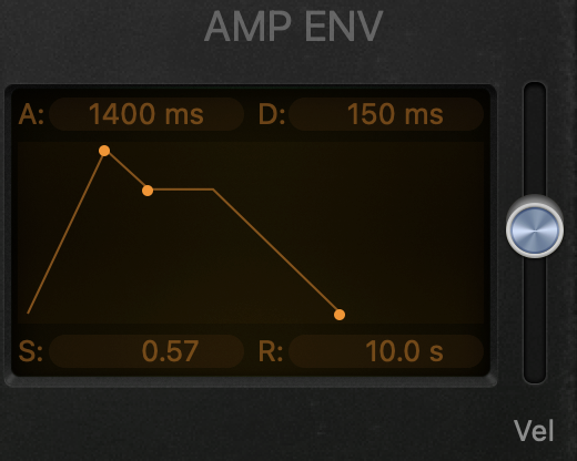
“A, D, S, and R,” in this picture, refer to “Attack, Decay, Sustain, and Release,” the four parameters of the envelope generator. This is the most common kind of envelope generator. If you’re not familiar with these parameters then I’d recommend reading this article before continuing.
This looks superficially similar to the envelope generator that we’ll be building, but it differs in some important aspects:
- The Retro Synth “envelope” is really more equivalent to a modular EG, VCA, and Mixer all wired together. There is some complexity hidden here.
- The Retro Synth envelope shown here is for amplitude (note volume) control only. (Retro Synth has a separate envelope which is hard-wired to filter cutoff or VCO pitch.) If you wanted to use an EG to modulate some other control, such as the effect mix, well, you can’t do that in Retro Synth. The EG module, on the other hand, can be connected to any other module with a CV input. (Some software synths are more flexible than Retro Synth in this respect and allow you to use an envelope to modulate any synth parameter.)
- With the Retro Synth envelope it’s possible to have a slow attack followed by a slow decay. As we’ll see, the mki x es.EDU module can’t do this, because it would have made the circuit more complex.
- The Retro Synth envelope’s attack, decay, and release rate controls are linear; the attack, for example, increases as a straight line. The mki x es.EDU envelope generator, on the other hand, follows a curve, which looks approximately logarithmic. Both sound fine, but you’ll hear the difference, especially with a slow setting.
One thing which is common to nearly every synth envelope but might not be obvious to people who have not used them is that the controls here are:
- Attack time
- Decay time
- Sustain level
- Release time
One of these things is not like the other! This will turn out to be surprisingly important in the discussion below.
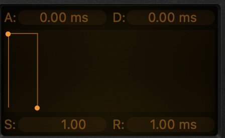
When using an envelope to control the note volume, you can change the shape of a note to be like an organ, which goes to full volume when you press a key and turns the note off when you release it:
…or a piano, where the note spikes briefly to full volume and then fades, eventually to nothing, as you hold the key. If you release the key during the decay the volume will immediately drop to nothing:
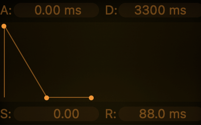
A real piano has a somewhat more complex decay, but the Retro Synth envelope can only do a linear decay. Other synths can do an exponential or arbitrary decay shape which will more accurately model a piano.
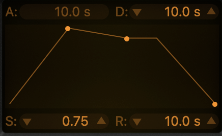
It’s pretty common to have envelopes which aren’t really modeled after acoustic instruments, for example with a “pad” sound. This might have a slow attack, a slow decay, sustain at 75%, and a slow release:
As noted, this is one of two envelopes in the Retro Synth plugin, which is quite simple and lacks a modulation matrix. Other synth plugins have additional envelopes which can be arbitrarily routed to modulate any parameter on the synth via a modulation matrix.
Modular Envelope Generators
With an Envelope Generator module, you can accomplish these uses by connecting them to other modules:
| Envelope use | Modular equivalent |
|---|---|
| Change volume of note as it’s held | EG connected to Voltage Controlled Amplifier |
| Change filter cutoff as note is held | EG connected to Voltage Controlled Filter |
| Change pitch of note as note is held | EG connected to VCO pitch CV input |
On a standard synthesizer you might have a separate envelope for each of these, a switch on the envelope, or a modulation matrix to choose between these functions. With a modular syntesizer, there is “just” an envelope generator, but you need to connect it to some other module to get it to do anything useful.2
A keyboard suitable for controlling a modular synth will have a “Gate” output which goes high when a key is pressed and low when the key is released. (Again, you don’t get chords, at least not without a surprisingly large amount of work.) So if you press a key for half a second and then release the key for half a second and repeat that cycle forever, the Gate output will look like a square wave with the low voltage at 0V and the high voltage at… well, it depends on the keyboard.
The Eurorack “Standard,” Redux
Reviewing some of the online comments, it seems that a few people had trouble with this module. Based on some of the comments there, it seems that once again people are getting bitten by the fact that the “Eurorack standard” is anything but! To be more precise, different keyboards and sequencers put out differing voltages on their Gate/Trigger output.
To quote from the Doepfer A-100 Technical Details document:
The gate level +5V shown in the picture is only an example. Within the A-100 usually any voltage beyond about +3V is treated as “high” (e.g. +5V, +8V, +10V, +12V will work) and will trigger an ADSR or any other module with a Gate or Clock input (e.g. trigger delay, sequencer, clock divider, clock sequencer). Any voltage below 1V is treated as “low”. If the specification of a module differs from this voltage standard it is mentioned in the description of the module in question.
The circuit in the mki x es.EDU Envelope Generator is designed to trigger at 3.8V. Quoting from the manual:
I’ve set up a voltage divider to get our reference voltage. A 100k/47k combination gives us approximately 3.8 V to work with. So whenever our input voltage is higher than that, the comparator’s output will jump to +12 V. And if it’s lower, it drops down to –12 V. Why did I choose that exact threshold? To be honest, mostly just because I had packs of 100k and 47k resistors lying on my table when I was testing this. But I still feel that 3.8 V is a decent value here.
Given the fuzziness of the specification, “because I had these packs of resistors conveniently at hand” is as good of a reason as any, and meets the Doepfer requirements.
I measured the output of my Novation SL MkIII’s Gate output, and it’s 5 V. People on the previosly referenced thread claim that the B*hr*ng*r Neutron is only 3.3 V. Which “kind of almost” conforms to the Doepfer text (“usually/about”!), but is apparently low enough to cause some heartache with this kit.
The instructions for the kit say:
To properly test this circuit, you’ll need a square wave LFO and a module with a CV input like a VCF.
In light of the above, you would want to consider your inputs carefully! You could use the VCO module, but probably not for the output and input of the EG. My pocket scope has a function generator built in, but it can only output a maximum of 2.5v peak to peak.
My recommendation is to measure the output of the actual device you’ll be using to control the module when you’re finished with it. I don’t typically use my keyboard when building the modules, as it’s big and I don’t want to carry it around the house, but I did take care to note its output. You don’t want to use one device when building a module and then be surprised by the power requirements of some other device when playing with the module.
Also, you might want to consider changing the resistor going into the comparitor if you require supporting gear with a lower output. R9 in the schematic is a 47k resistor. If you substitute a 33k restistor instead, then I calculate that you’ll change the trigger threshold to 3 V, which is maybe a better default?
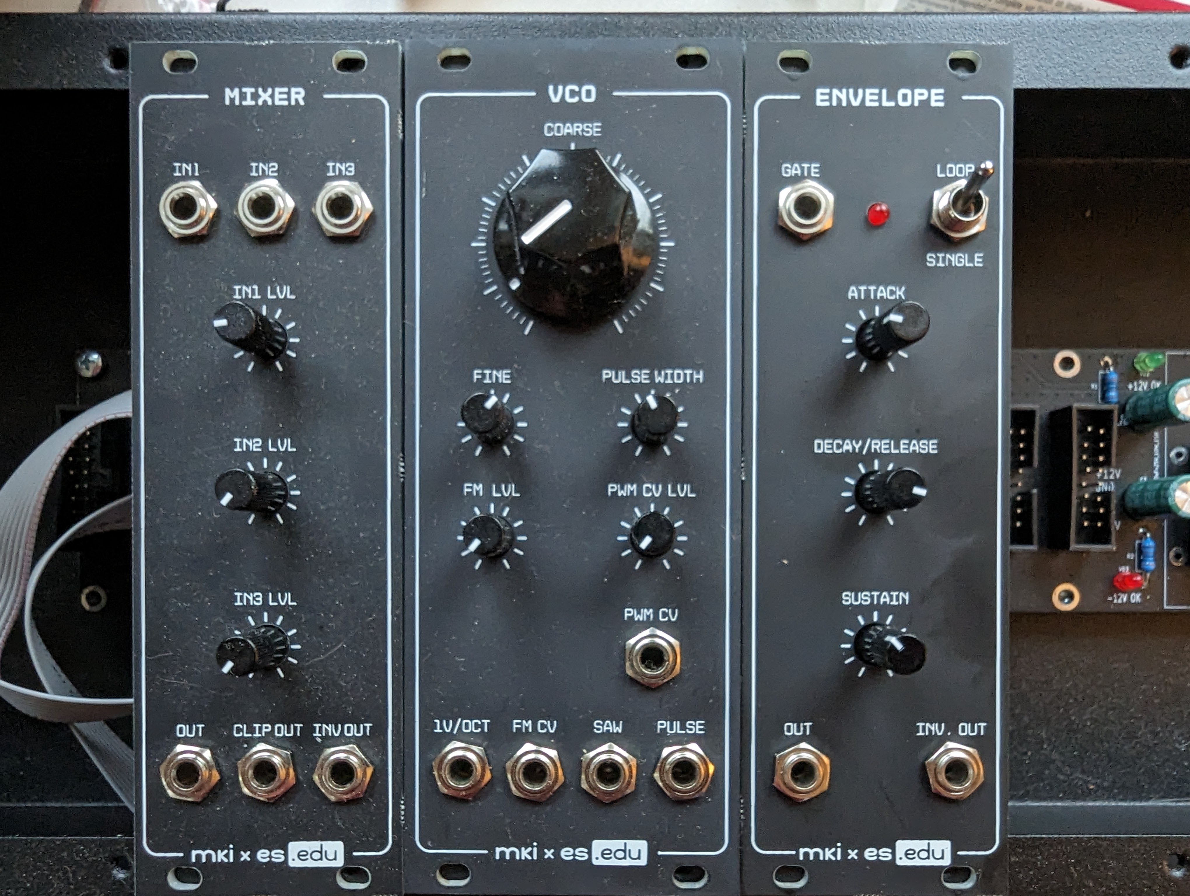
The mki x es.EDU Envelope Generator
Fundamentally, the way that the mki x es.EDU Envelope Generator module works is that it applies a low-pass filter to its Gate input. A low-pass filter will tend to round off the corners of a sharp change in a signal. This turns what looks like a square wave (presuming that you’re pressing and releasing a key at a constant rate) into a smoother shape.
In the first iteration which you build on the breadboard it applies only one lowpass filter to the gate, giving you a more rounded shape. Then, by using a pair of diodes, two separate lowpass filters are used in the circuit, one for the rise, and a separate filter for the fall (see example on the right).
That’s simple enough, but it’s a little too simple, even for these circuits, as just a couple of filters would allow you to control the attack and the release but not have a sustain. So, as you’ll see, things become a bit more compliacted.
Breadboarding the Envelope Generator
Passive vs. Active Circuits
We start by building a passive EG, but as you can’t hook it up to anything which draws more current than an oscilloscope without changing the envelope, that’s really only good for demonstrating the principle of operation of the EG. Building a “useful” EG will require some op amps.
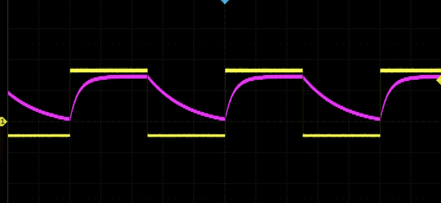
If you look at the “Passive trace” figure on the right, the yellow trace is the square wave I am using as the input to the EG, and the purple trace is the output of the EG. As you can see, the output of the passive circuit is limited to the voltage of the input to the EG (which, as previously noted, is not consistent between different keyboards you might use to produce that input). Also, the output impedance would not be handled well; the shape of the waveform would change depending upon what you connected to the EG’s output.

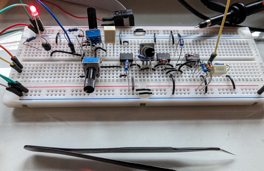
With the active EG the output voltage (see the “Active trace” figure) is now independent of the input voltage, and the impedance would be better handled, due to the use of a buffer op amp. Here’s what that looks like on the breadboard:
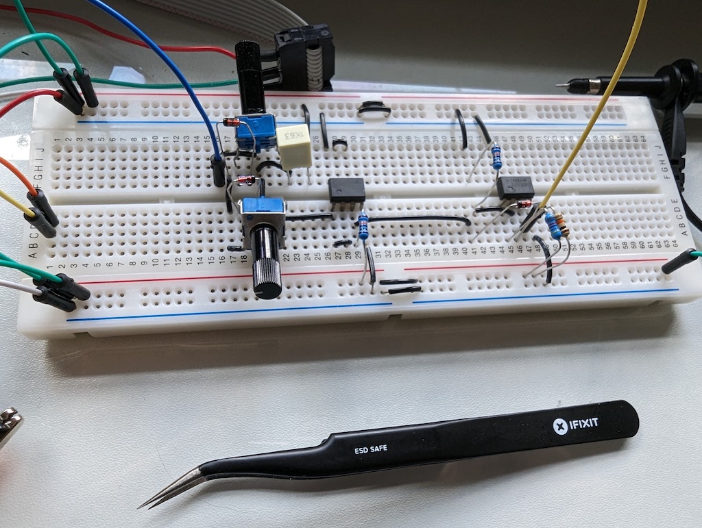
(If you look really closely at this photo you’ll notice an extra resistor I’ve added to bring the voltage threshold down to about 2 V to start the EG. As noted above, my function generator has a limited voltage range.)
Attack, Decay/Release, Sustain Controls
I’m going to explain how the attack and decay are implemented in the circuit. This is, ironically considering it was done to keep the circuit itself simple, somewhat complicated to understand, so feel free to skip ahead to the next section if you’re so inclined.
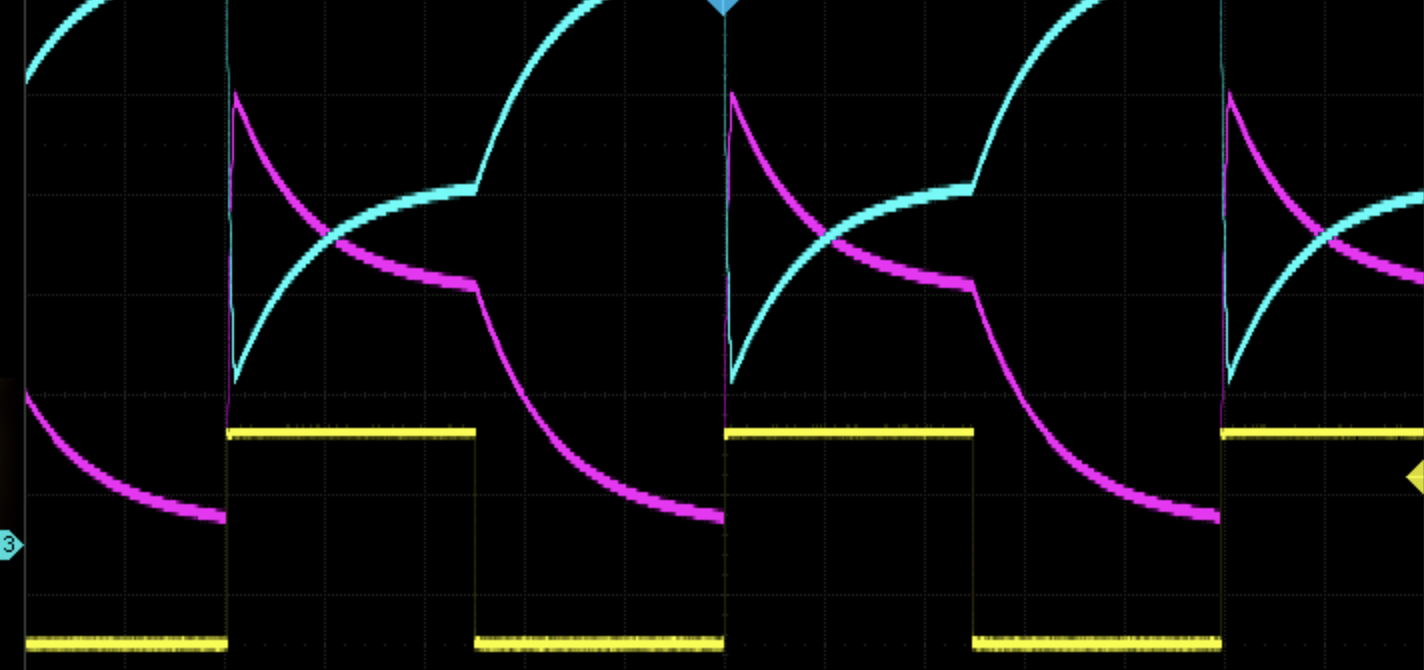
In the images in this section, the Gate input is the yellow trace, the EG output is the purple trace, and the internal signal which the EG mixes into its input before shaping it with the filters is the cyan trace. The envelope starts at the center of the screen, not the left side.
The way a “real” envelope generator works on a commercial synth works is first the attack happens, taking the envelope to its maximum level. Then the decay, as it goes to the sustain level, and finally, when the key is released, the release happens.
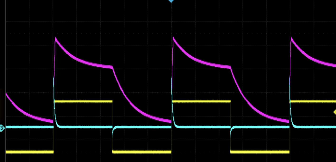
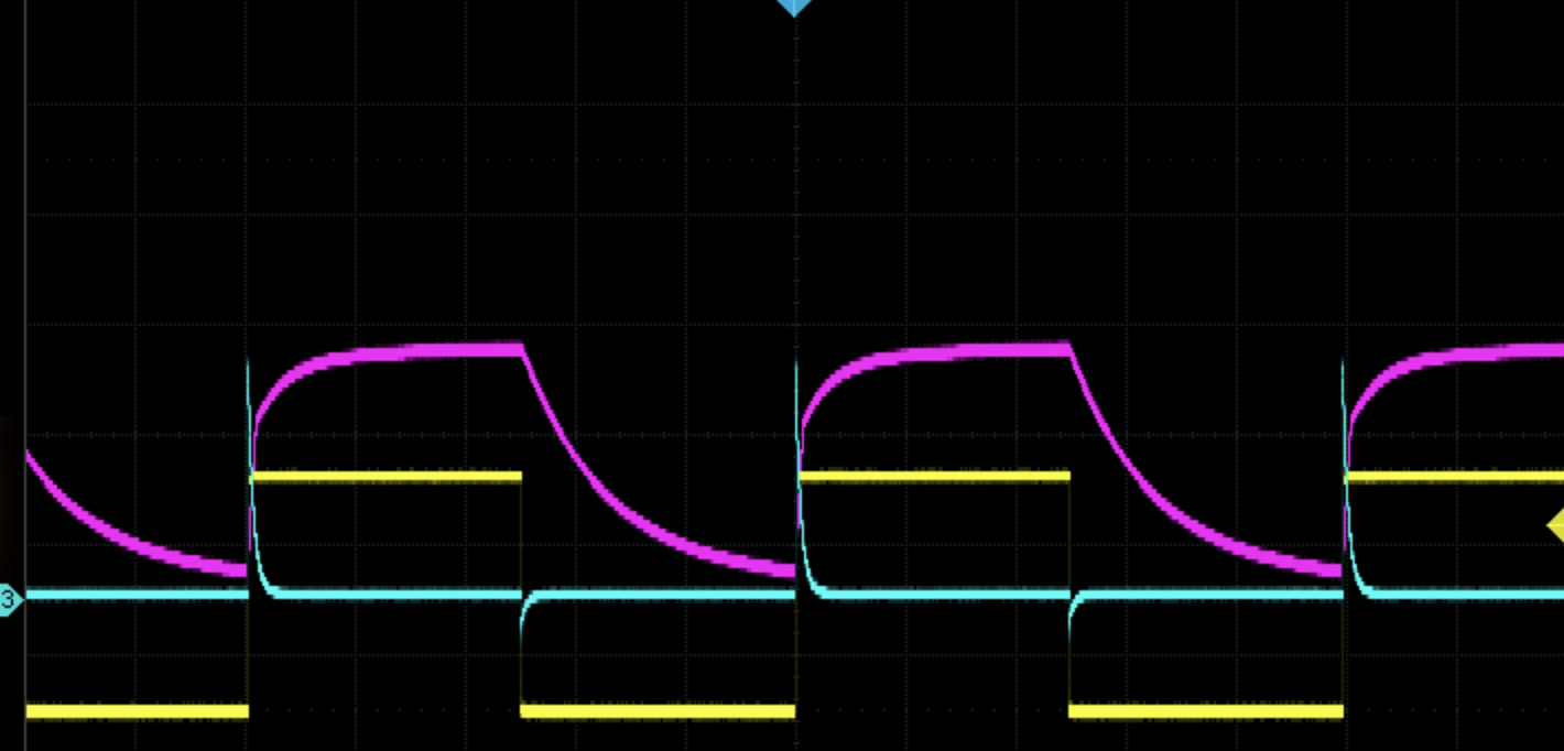
With the mki x es.EDU kit, on the other hand, the decay only has a chance to happen when the attack is quite short. If you look at the “ADSR trace” on the right you can see that with a short attack, the decay can happen, followed by the sustain and release. This is the “best case scenario” for this circuit. With roughly this shape, you can adjust the attack (a little!), the decay/release times as a single value, and set a sustain level.
When I dial in a longer attack, there is no decay; in this case the attack takes its time to even arrive at the sustain level, wherever that happens to be set. Importantly, the attack in this case only goes to the sustain level; it does not go to 100% as a standard synthesizer attack would do (even with this long attack).
Note how the attack level is much higher in the “ADSR trace” example, and how the attack only goes to the “sustain” level in the “ADSR trace with slow attack” example.
This is because of how the EG works. If you look at the figure called “ADSR trace with slow attack,” you can see a third, cyan trace. The cyan trace has a pulse which is fired when the input goes high. As you can see, the pulse is pretty short. One way to think about the duration of the pulse is that it’s the maximum length of time your attack can be for there to still have a separate decay. You can have a longer attack, yes, but if you do then:
- You won’t get any decay, and
- Your attack will only go to the sustain level, not to 100%.
One way to think about the mki x es.EDU EG is that it’s two low-pass filters on the sum of the gate signal and the internal control signal (one filter controls the speed of the attack; the second controls the speed of the decay and release). The lower we set the low-pass filters, the more we round the corners of the square gate signal into smooth curves.
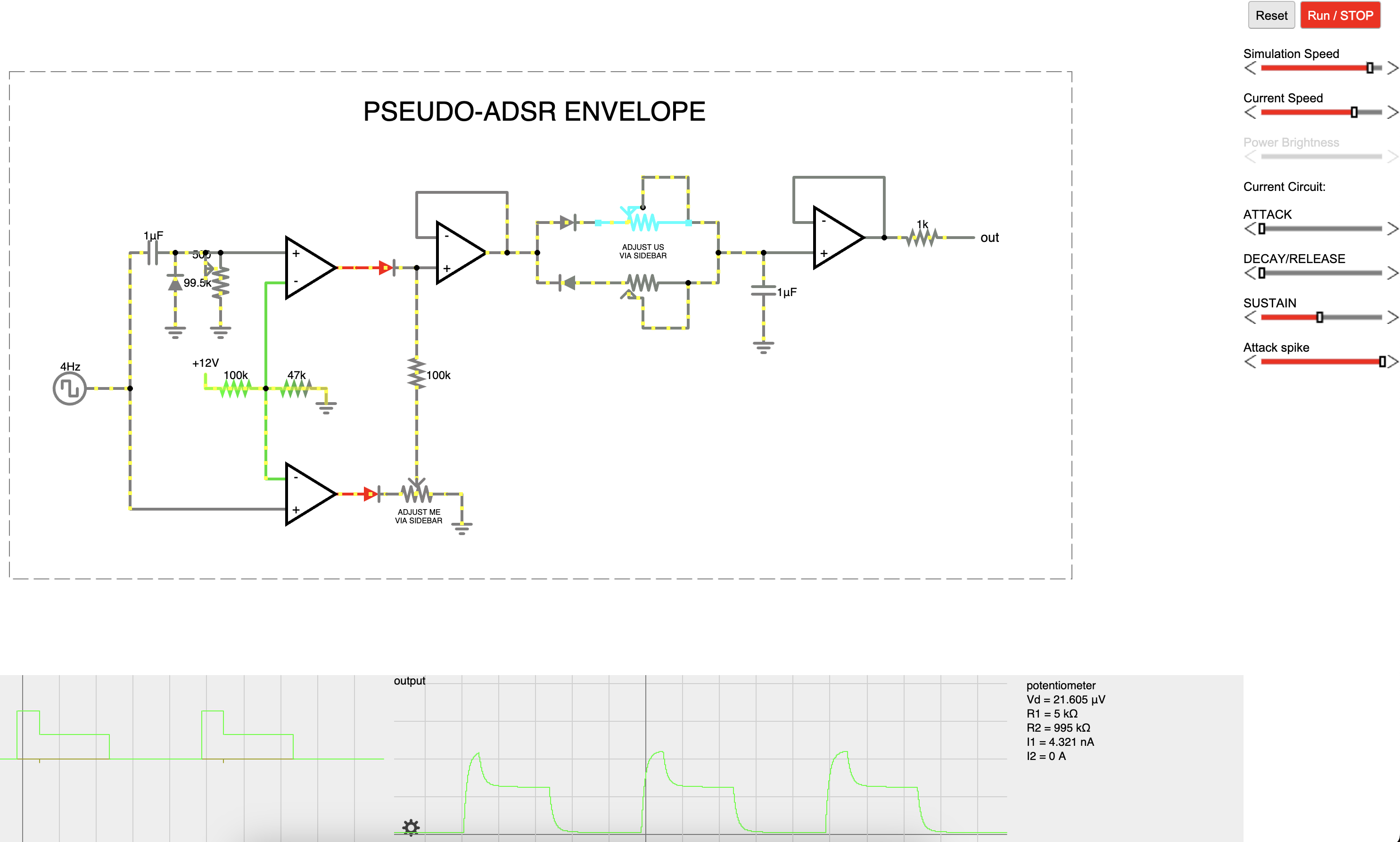
The envelope needs a sustain, and that can’t be accomplished with just filters. So instead of filtering the Gate signal directly, instead it first produces an internal control signal, represented by the cyan trace in the images just above. The EG generates a pulse at the start of the Gate similar to the “Trigger” output that some keyboards have, and separately reduces the gate down to a sustain level which you can adjust with a potentiometer. These two signals are mixed together, forming a shape like the cyan trace below. Just like before, you can vary the attack speed with one pot and the descending phases (decay and release) with another pot.
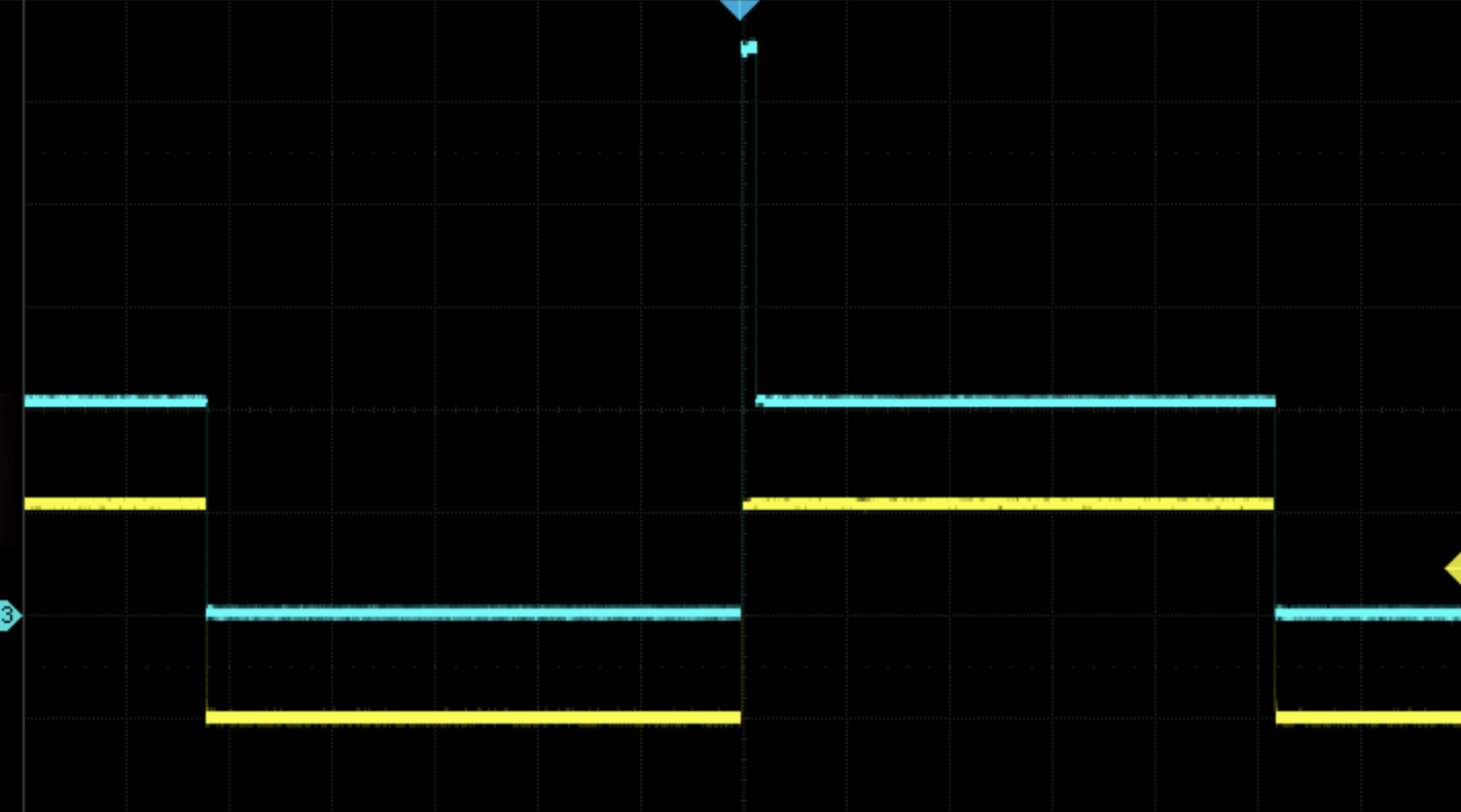
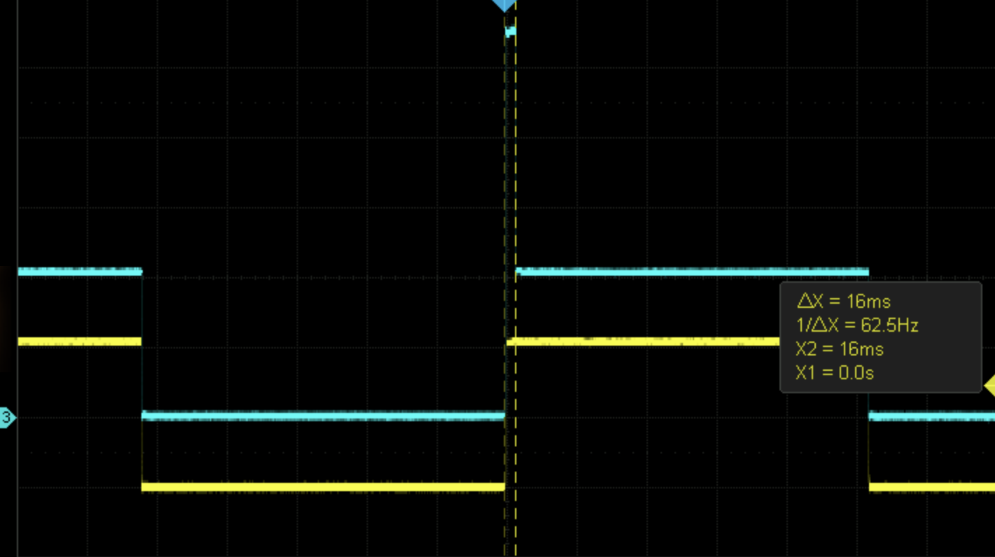
In this example the input the the EG is shown in yellow and the wave which the EG will round off using filters to become its output is shown in cyan. The high pulse on the left always goes to 100%, and the sustain for the rest of the cycle is settable by the user. Here I’ve adjusted it to around 50%. The width of the pulse on the left is not assignable by the user; it’s always small; here I have measured it at a about 16 ms.
So, if you use anything besides a very short attack then it will take longer than the pulse at the beginning of the envelope and will go to the sustain level instead of all the way to 100%.
LED
I added an LED, and a transistor to drive it.
Inversion
This time the blue trace on the right is showing the inverted output. No surprise there; it uses an op amp in an inverting configuration to produce this output.
Looping the Envelope
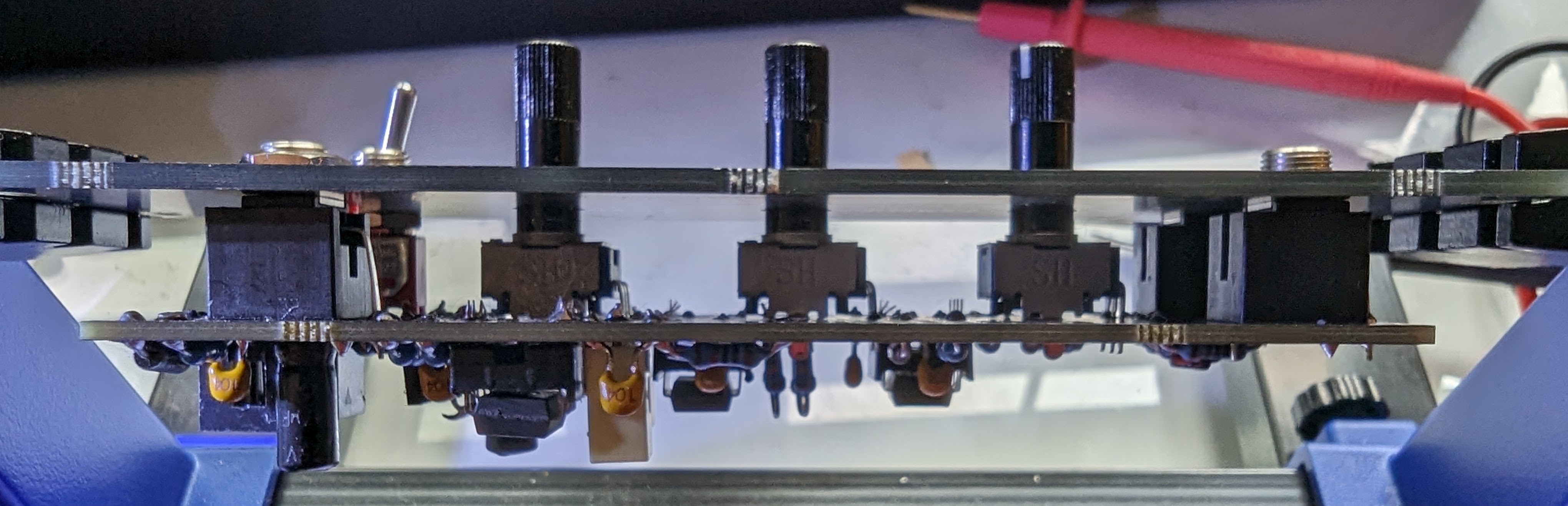
I found this section somewhat hard to understand, not least because the directions lead off with a confusing bit of language:
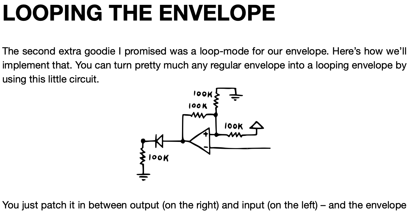
I had thought this was a mistake; the input is on the right and the output is on the left. Looking at the circuit simulator seemed to confirm this. It was only when I watched Moritz’s YouTube video that I realized he was talking about the envelope generator inputs and outputs, not the I/O for the Schmitt trigger circuit pictured above. The output of the Schmitt trigger goes to the input of the envelope generator, and vice/versa!
In the end the way that this produces a loop is pretty simple, and here’s how I would explain it:
First, this circuit produces a specific type of loop. Namely, it loops whenever the envelope output goes to zero. This is quite reasonable, but it confused me as it’s not the sort of loop which you would get if you connected an LFO to the gate input of the EG, which would always happen on a certain timeframe regardless of where the envelope is in its cycle. The EG’s loop circuit always happens after the release.
Given that requirement, then we just need a circuit which will make the input go high whenever the output goes low. That sounds like a Schmitt trigger inverter, something which you’ll be familiar with if you’ve previously built the mki x es.EDU VCO, and the circuit shown is just building a Schmitt trigger inverter using an op amp and a few passive components.
However, my confusion only got worse as I looked deeper into this step. I had found the breadboard diagrams increasingly difficult to line up with the schematics as the breadboard got more densely packed, and I ended up annotating the diagram in this step. It differs from the schematic in the step in a couple of important ways, and all of the jumpers and the unlabeled pots, op amps, and jacks had finally pushed past the point where I could keep track of this in my head.
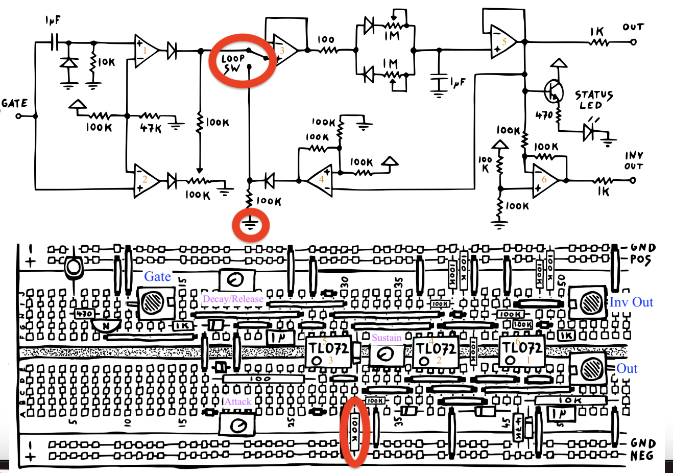
These are mostly the same as the diagrams from the manual, only I have added all of the colored annotations. Note, especially, the red circles. The breadboard version of the circuit does not include the switch (the components for the Gate input section are on the board, but they’re “permanently switched off” in this version), and in the breadboard version the resistor goes to the negative rail instead of ground. That last bit just seems like an error to me – the full schematic and the PC board layout later in the directions match the schematic here. So I ended up not doing this part.
The Mistake I Made
Another problem I had during the breadboarding of this circuit was at one point I mistakenly connected my oscilloscope’s ground clip to the -12V rail instead of ground. This made the output very distorted and caused the power supply to the synthesizer to start getting hot. It took me a while to find the issue because the way you route power to breadboards with two power rails when you need three is a little consuing. The video about why this is a bad idea is literally called How NOT To Blow Up Your Oscilloscope!
Modifications: Can We Fix the Limitation on the Attack?
The limitation to very short attack times is somewhat less than ideal, so could we fix it? The “pulse” used to generate the attack is set to a pretty short duration, and it’s not adjustable. What if it were adjustable? That’s not so hard. We could replace the attack potentiometer with a stereo potentiometer (which is really just two separate potentiometers with a single shaft to adjust them). Then we could use one of these for the attack time, as before, and the second for adjusting the width of the pulse.
So I tried this out in the circuit simulator, and it seems to work, for the most part. (Except that the falstad.com simulator has no stereo potentiometers; I had to use two mono pots with separate adjustments.) But I can certainly make the attack longer by increasing the resistance of what used to be a single 10k resistor and is now a potentiometer. Overall it feels like an improvement.
Actually including it in the final project would require changes in packaging since the stereo pot is larger than a mono pot, and changes to the circuit. More importantly, I would need to tweak the resistor/capacitor values in the lowpass filter at the input so that the range of the pot was correct for both the pulse length and the attack curve across the full range of the stereo pot.
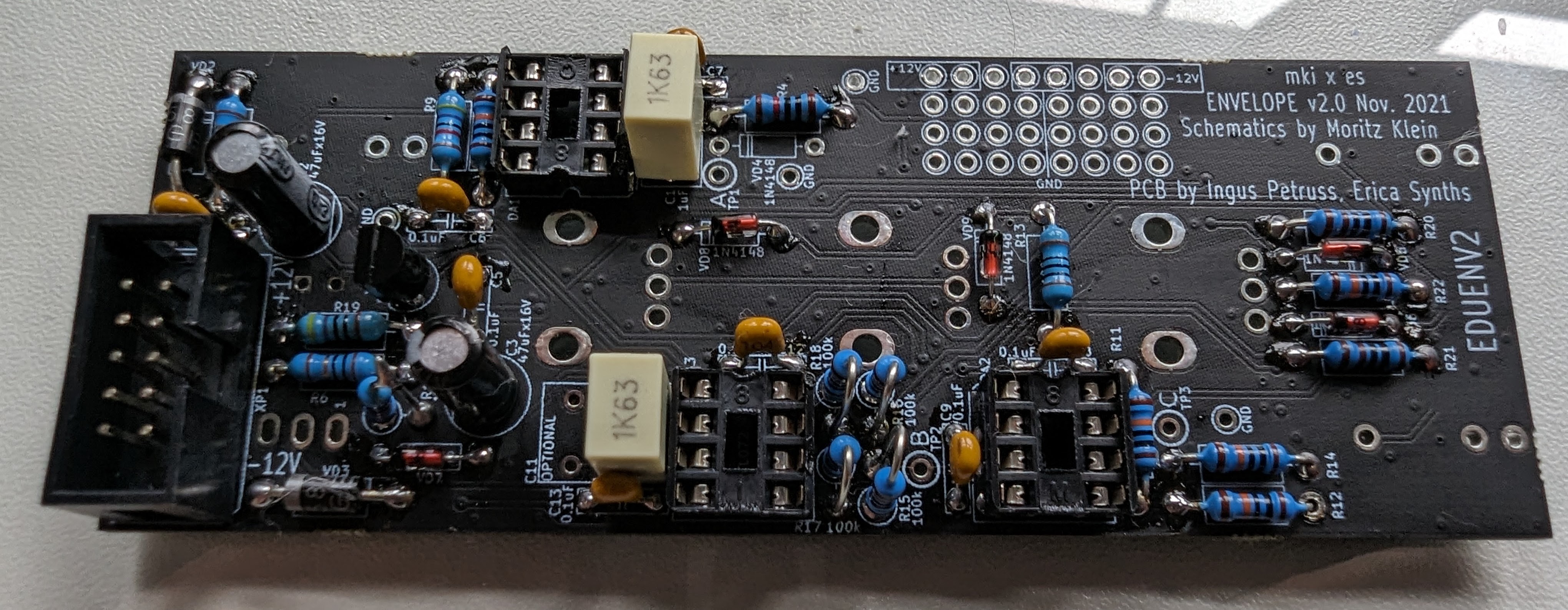
Building the PC Board
This all went very smoothly except at one point I mixed up a 100 k and a 100 ohm resistor. These two are very different! I fixed this before powering the circuit.
Resources
Instructions
Community
Simulations
- Simplest Envelope
- Passive A/R Envelope
- Active A/R Envelope
- Pseudo ASDR Envelope
- Status LED
- Inverting Buffers
- Looped Envelope
Videos
- Introducing the mki x es.EDU DIY EG kit by Moritz Klein (5:03)
- Designing a simple ADSR(-ish) envelope generator from scratch by Moritz Klein (30:59)
- How to loop any envelope by Moritz Klein (2:48)
- Erica Synths .EDU Envelope - Building and Demo by Synth DIY Guy (18:05)
I chose this comparison because Retro Synth is a very simple plugin. Other plugins such as Alchemy allow you to add an arbitrary number of envelopes routed to any parameter on the synth, having very complex shapes. That would be a huge digression here.↩
In this sense the EG module is more like the envelopes in Alchemy, which can be used to modulate literally any knob on the soft synth, than the envelopes in Retro Synth, which are “hard-wired” to just three parameters. Logic Pro also has a “Modulator” Midi Effects plugin, which is a bit more like the envelope generator we’ll be building here in that it can be connected to nearly any plugin parameter, and functions both as an envelope generator and an LFO.↩