Building a Synthesizer, 4
A Gentle Introduction to Op Amps
- Introduction: The World of DIY Synthesizers
- 1: The mki x es.EDU DIY System
- 2: Building the Power Supply
- 3: Breadboarding the VCO
- 4: A Gentle Introduction to Op Amps
- 5: Building the VCO
- 6: The Logic Circuits Model of Computation
- 7: Building the Mixer
- 8: Building the Envelope Generator
- 9: A Field Guide to Oscillators
- 10: Building the VCA
- 11: Debugging Circuits and Software Debugging
- 12: Breadboarding the VCF
- 13: Building the VCF
- 14: Building the Sequencer
- Glossary and Electrical Connections
There are approximately 11868 op amp tutorials on the web. I’m going to add the 11869th one, because op amps are really important, and because I don’t think most of the existing explanations are as clear as they could be. I think I can improve on these in two ways:
- By
telling you a bunch of liesexplaining concepts in terms of gross but useful overgeneralizations - By going slowly and explaining them in terms of “increasing levels of detail”
So let’s start out easy.
This is a long article and there’s no need to read it all in one sitting. But each “Level” builds on those which come before it, so make sure you understand Levels 0-4 before you start reading Level 5. However, each “Level” is self-contained, which is to say that if you read to Level 2 and you don’t want to read any further, that’s fine; I’ve tried not to spread important concepts across multiple levels.
Feel free to reach out if something doesn’t make sense to you.
Level 0: What Is an Op Amp?
An op amp, short for “operational amplifier,” is a circuit (details unimportant,
at this point), which is widely used in analog electronics in general, and, of
interest to people who might be reading this series, analog synthesizers. It has
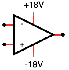
two inputs and one output, although multiple op amps are often packaged onto a
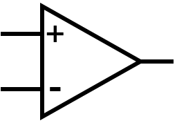
single integrated circuit. One input is called the + or non-inverting input and the other
is called the - or inverting input. There is one output (which is on the
right, in the diagram below).
Like may stories I will tell in this post, this is a lie, but it’s a white lie. There are a bunch of details I’ve omitted. We will get to those as they become relevant.
When you’re looking at a schematic and see the symbol above, you can say, “Aha! That’s an op amp.” You’ve already learned something useful!
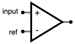
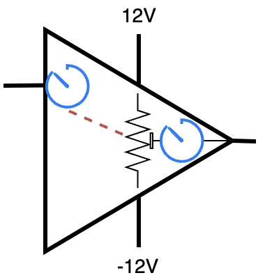
Not every component with a triangle and a + and - input is an op amp. This
is not an op amp:
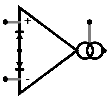
The above is… well, don’t worry too much about what it is; that’s not what this article is about. The important point is that when you see something which looks like the first picture in this article, that’s an op amp. When you see something which looks sort of like an op amp but has a bunch of extra stuff, then it might be something different.
The “operational amplifier” gets its name from the op amp’s ability to perform certain mathematical operations on an input. We will give specific examples in the next level, but if you’re wondering where the name came from, now you know. An op amp can be used in a number of different configurations to provide useful features (“operations”) in a circuit. They are widely used in analog audio electronics. They are not the only kind of amplifier in use, but they are one of the most common.
Level 1: How Can I Use One?
There are a number of circuit “configurations” — properly, these are just “circuits,” but I tend to call them “configurations” to make it clear that they are sub-circuits of some larger circuit — that you can build with an op amp.
I’m not going to explain how these circuits work in Level 1. I’m just going to show some useful things you can do with an op amp.
I will give five useful configurations of an op amp in this article. There are, of course, more! The examples below are just that, examples, not a complete list of everything you can do with an op amp.
Buffer
The buffer copies a voltage from the + input to the output. In the schematic,
below, the input is at the upper left and the output is on the right. Throughout
this article I will try to stick to that convention, although in a “real”
schematic both may be anywhere.
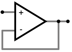
Don’t worry about how it copies the voltage right now. Just take my word for it that the circuit in the schematic will copy the voltage.
Incidentally, this is the same way that an expert views these circuits. They don’t start by thinking about how much voltage the op amp is emitting. They look at a schematic and recognize, “oh, that’s a buffer.” They understand how it works, but they don’t think about the precise mechanism, at least at first. Later on they might look more deeply, and so will we! This is a little bit like when you know how to read words in a sentence you don’t have to look at every letter of a word and sound it out unless it’s a word you’re unfamilar with.
Copying a voltage sounds sort of useless, but it does this in a way which doesn’t draw any current from the input. Also, no matter how much current is drawn by an external load at the output the voltage at the output does not change. Both of these are very useful properties!
This sort of buffer is widely used in audio circuits, among many other applications. If you plugged a pair of headphones into an output without such a buffer, the headphones impedance (resistance to audio signal) might interfere with the circuit which produced the audio signal. The buffer prevents this and ensures that the signal produced by the audio circuit is the same signal you hear in the headphones.
Some other names for the “buffer” configuration are the “unity gain amplifier” or the “voltage follower.” They mean the same thing.
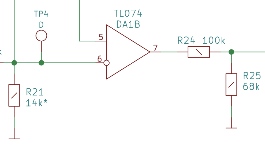
Here’s an example of an op amp in a “buffer” configuration in a real circuit:
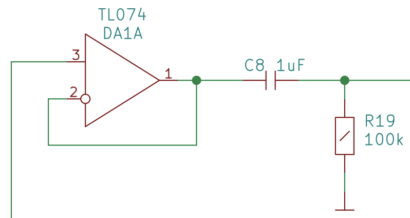
The symbols are different in this schematic. We will just have to live with that. People don’t always use the same symbols. There’s no right or wrong.
I have included some of the other components in this detail from the schematic to emphasize that you will need to be able to pick these configurations out when they are surrounded by other components.
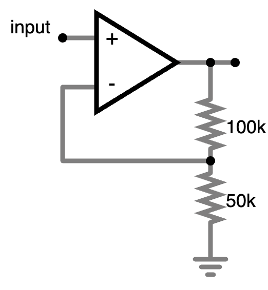
Amplifier
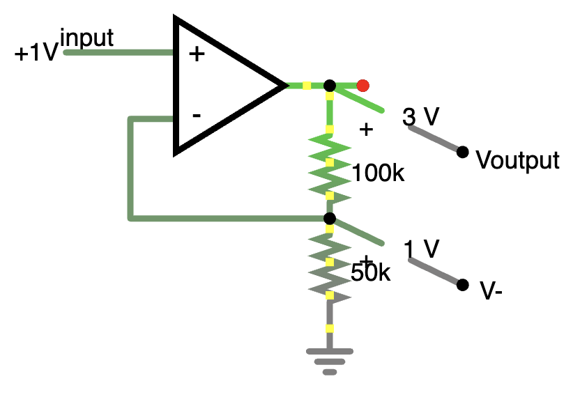
The amplifier takes a voltage at its input and sets the output to a voltage which is some multiple of the input voltage.
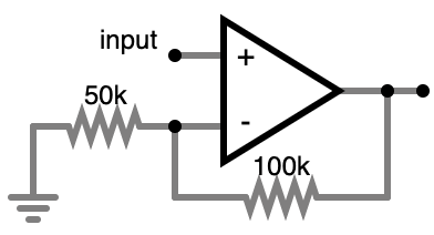
In this specific case, with these specific resistor values, the voltage at the
output is 3* the voltage at the input (within
certain limits). You can change the amount of gain by changing the
resistor values. In the extreme case, where the resisitor going to ground is
infinite (no wire at all), and the resistor going from the output to the -
input is 0 Ohms (a plain old wire), this circuit is the same as the “Buffer”
configuration above. So the buffer is just a special case of the amplifier,
only the buffer has a lower gain (amplification factor) of 1 (meaning no amplification).
One thing you can’t do is have a gain of less than unity – to have an output voltage less than the input voltage. But you can do this with an inverting amplifier, which we’ll discuss in a little bit.
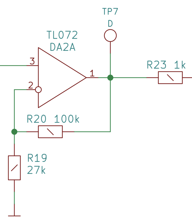
Here’s an example of an op amp in an “amplifier” configuration in a real circuit:
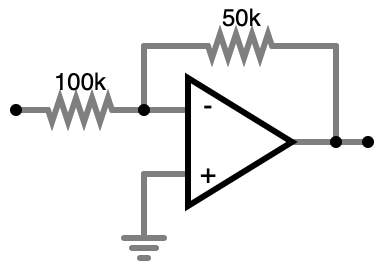
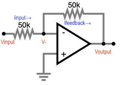
Inverter
The inverter turns a signal upside down. For example, you might have an input signal which alternates between 3V and -5V. The inverter would turn that into a signal which alternated between -3V and 5V.
You connect the input signal at the far left hand node in the schematic above. Don’t worry about what the resisitors are doing in the circuit just yet, or why this circuit inverts the signal. Again, just take my word for it that this circuit will invert its input. I will explain how it works in a later level.
Like the “amplifier,” this circuit also has two resistors, but they’re in a different place, which makes the circuit do a different thing. Again, don’t worry about how it works right now.
Do note that I’ve switched the inputs in this diagram, putting the - input
on top. The only reason I’ve done this is because it allows me to keep the input
to the circuit in a consistent place (the input signal which we want to invert
should be connected to the - input via a resistor), and because it allows me
to run the ground which is connected to the + input in a downward direction,
which I find aesthetically pleasing. You can draw the diagram either way.
Here are two inverters in a row from the Mixer schematic. It inverts the signal twice!
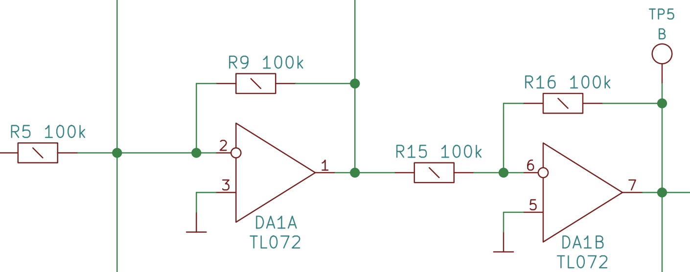
Why would it do that? It’s discussed in the mixer instructions. But it’s a little premature for us to discuss that until we talk a little bit more about how op amps work.
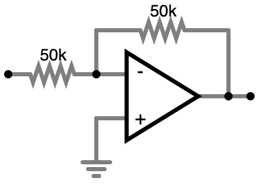
Inverting Amplifier
This diagram should look very familiar, because it’s exactly the same as the one I showed for “inverter,” only the value of one resistor has changed.
In this case, I’ve set the resistor values such that the amplifier has a gain of -0.5. So if for example you connect 5V at the input, you will see -2.5V at the output.
The “non-inverting” amplifier configuration could only have a gain of greater than or equal to 1. But the inverting configuration can amplify by a factor from 0 to “negative infinity.” (A lie, in the real world it’s really somewhere in the neighborhood of -100000, but it will do for what we’re building.)
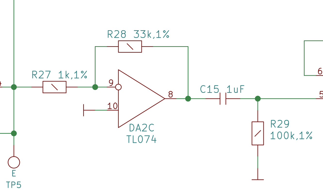
Here is an op amp in an “inverting amplifier” configuration from the VCF schematic.
Comparator
The comparator compares the voltage, Vinput, at the + input with
the voltage, Vref at the - input. It sets the output “high” if
Vinput is higher than Vref and “low” if Vinput
is lower than Vref.
“High” and “low,” here, mean “as high of an output as the op amp can produce, given the power we provide to it,” and similarly for low.
Eagle-eyed readers may notice that this circuit diagram is the same as the one of the “plain” op amp in “Level 0: What Is an Op Amp.” So yes, this “circuit” is just a plain op amp with no extra components.
Despite its simplicity, this turns out to be a very useful circuit in some cases. For example, in the VCO kit we use an op amp in comparitor mode to produce a PWM wave from a sawtooth wave. (See that post for details.) It looks like this:
Level 2: Power Up
Perhaps you’ve thought, “Amplifier, huh? That power has to come from somewhere!” If so, give yourself a pat on the back; you’re right! We need to supply power to the op amp. The amount of power required will depend on the particular chip you’re using.
Every once in a while, only very occasionally, you will see these power inputs in the schematic with the op amp itself:
When these power connections are labeled at all, they’re often called Vcc+ and Vcc- or V+ and V-, but they’re usually omitted from schematics at the point in the circuit where the op amp is used. You should know that the power connections are there and the op amp won’t work without them, but they tend to be omitted from schematics in order to keep the schematic simpler.
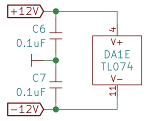
The power connections might be elsewhere on the schematic. Here’s the section of the VCO schematic showing the actual power going to the chip. The op amp itself is not shown here; that’s elsewhere in the schematic. In this example the power goes to pins 4 and 11 on the chip. The remaining pins are for the op amps themselves and these appear elsewhere in the schematic.
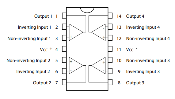
There are 4 separate op amps on the TL074 chip. The op amps and their power supply are just different pins on the same chip. Here’s a pinout:
Although an op amp’s gain is very high (more on this below), the op amp can’t ever output any voltage greater than the voltage connected to the Vcc+ input, and it can’t ever output any voltage lower than the voltage connected to the Vcc- input. Actually, the true values are even lower; the TL074 data sheet says that its actual minimum/maximum output level is 1.5V below Vcc. So the VCO output in this case is limited to approximately +/- 10.5V.
One thing that a lot of people notice is that there is no ground input to the op amp IC. There does not need to be one because the op amp IC’s internal circuit does not directly use a ground, and, somewhat like a transistor, instead depends on the fact that the output and the input circuits are grounded to a common rail.
So a “complete” circuit might look like:
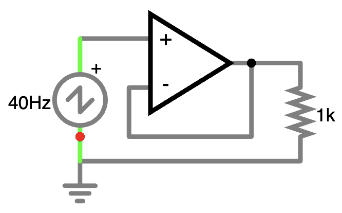
In this example, the input to the op amp is a 40Hz sawtooth oscillator, and the load is represented by a 1k resistor, which would probably be something more interesting in a “real” circuit.
Level 3: The “Ideal Op Amp”
In electronics, it’s pretty common to describe components in terms of ideals. We commonly say that a certain circuit contains a “100k Ohm resistor,” and only occasionally do we note that the resistor is a 1% tolerance model and might be anywhere between 99k and 101k Ohms.
Op amps are more complicated than resistors, and we often talk about the notion of an “ideal op amp” explicitly. An “ideal op amp” has infinite gain, infinite input impedance, zero output impedance, infinite bandwidth, and zero noise. Don’t worry much about what the terms in that sentence mean right now; just know that we build with physical op amps which are not ideal because they are built with actual silicon and not pure math.
Still, the notion of an “ideal op amp” does help us to understand how an op amp works. If the gain of an op amp is merely very high, that still sounds like something we could control, if only we could build a circuit which is sufficiently precise. But if the gain is “infinity,” then that sounds very challenging to control. This is the correct intuition! If I tell you that the output of an op amp is proprotional to the difference between the two input voltages, you might be tempted to try and set both of those voltages to a correct level as you would with a transistor. But if I told you that the output is “the difference between the two voltages, times infinity,” then you would quickly give up on setting both of the input voltages to some value which would give you the desired output voltage. Again, this is the correct intuition!
So we need some other mechanism for controlling the output voltage, and that mechanism is feedback. First we will look at what happens when you don’t use feedback, and then we will look at what happens when you do.
Level 4: How an Op Amp (Actually) Works (Without Feedback)
I’m going to tell you how an op amp works, but it will be confusing at first. Stick with me for a second!
The output voltage is the difference of the two input voltages, times some fixed gain. The fixed gain is hard-wired inside the chip and is set to a very large number, very roughly 100000. There is a limit on how high or low the output can go, however; namely it’s limited to within the range Vcc- through Vcc+, and actually the output range is a bit smaller than that.
There’s a lot going on in the sentences above, so let’s break that down a bit.
When we talk about “the difference between the two input voltages,” there are really two cases we are interested in:
- Those cases with feedback (“Buffer,” “Inverter,” “Amplifier,” “Inverting Amplifier”)
- The case without feedback (“Comparitor”)
Let’s consider the case without feedback first.
Comparitor
How does the comparitor work in light of the section above? In this case, and only in this case, we have input signals connected to both of the inputs of the op amp.
I am calling the voltages applied to the inputs “Vinput” and “Vref”
When the voltage at the + input (Vinput) is higher than the voltage
at the - input (Vref), the difference:
$$ \begin{align} V_{input} - V_{ref} \end{align} $$
…is a positive number. Let’s say that Vinput is 5 and
Vref is 3. The op amp multiplies this result, 2, by the very large
gain, and immediately sets the output voltage to 200000V. Or tries to. Remember,
the output voltage is limited by the voltage going into the Vcc+
power input, which is something far more reasonable, like 12V. So the op amp
does the best it can and sets the output to about 10.5V, which is the largest
amount of voltage it can emit.
If Vinput was smaller than Vref, then their difference would be negative and the op amp would swing the output hard in the other direction, attempting to set the output voltage to -200000V or so, but quickly hitting the limit of Vcc-.
And that fully describes the comparitor case; when the + input is higher than
the - input the output goes high, and when the + input is lower than the -
input the output goes low.
Weird, huh? If that were the only application for an op amp, you’d have to believe that there might be a simpler solution. But of course there are other use cases.
Level 5: Feedback
If there is one difference between digital and analog
electronics which I have found, it is this: The digital electronics designer’s
maxim is “make it as accurate as possible,” whereas the analog designer’s
North Star is, “if when you can’t make it accurate, make it adjustable.”
The genius of feedback is that it makes this adjustment automatic. This is the key to understanding the circuits in Level 1: They are all just different configurations of feedback.
The notion of using feedback as a mechanism to ensure precise control of an amplifier might seem counterintuitive at first. If I think of feedback in terms of amplifiers, I think of a guitar player with their guitar inside the cone of a Marshall stack, not exactly the image of precision and control.
But feedback is any connection of the output of a circuit to an input. This can be:
- Positive feedback, which makes the circuit go out of control, as with the guitar amplifier. Each time the amplifier amplifies a signal which it produced it gets louder and louder. An op amp doesn’t actually need a guitar player to hold them inside a speaker cone to go out of control; they do it perfectly well on their own in the absence of…
- Negative feedback brings the signal under control. Each time the amplifier reacts to its own output it gets quieter.
I’m not going to use the terms “positive feedback” and “negative feedback” in the rest of this post because I think they’re easily confused with positive and negative voltages, which are something altogether unrelated. Instead I will just talk about “feedback,” by which I am referring to the negative kind.
Reading “Level 1”, you might marvel at how many things an op amp can do just by changing the values of a few resistors! How can one simple component do so much?
Remember the “buffer” configuration from “Level 1?”
One way to think about the buffer is:
In this model, there are two voltage meters, one at the +
input of the op amp and one at the output. There is also a potentiometer
connecting the op amp’s power to the output, and a linkage which ensures that the
voltage going out of the circuit is the same as the voltage read at the
+ input. When the input voltage goes up, the linkage adjusts the output power
until the output voltmeter has the same reading. This is not how an op amp
actually works, but it’s a reasonable model of how it works.
Hopefully this will give you an
idea of how feedback works. Something is measured (the voltage at the +
input, in this case), and then something else (the potentiometer) changes based
on that value.
Importantly, this circuit is self-correcting. If the potentiometer is 5% tolerance and varies in its actual value in ohms, it will just tweak the potentiometer setting until the two volt meters read the same.
At this point you might think, “That’s all very neat, but why bother with all of this feedback business? If you want a 2* gain, why not just, you know, set that and be done with it?” It turns out that this is kind of hard! You can amplify with a transistor, sure, but the transistor will be highly variable depending upon its temperature. By controlling the amplification factor with the ratio between two resistors, which:
- Are less temperature-sensitive than transistors
- Produce far less of their own heat at the currents used here
- Tend to change temperature in unison due to room variations or current, preserving a fairly steady ratio between them
You can have very accurate amplification factors even when dealing with the “messy” analog world.
Level 6: How an Op Amp (Actually) Works (With Feedback)
Understanding the behavior of the op amp with feedback is just slightly more complex, because it varies a bit over time.
In the examples below, I’m going to presume the op amp’s fixed gain is 100000. In reality, we don’t know the exact number (it varies a bit with temperature and other factors) but this is in the right ballpark. As you will see, the exact value isn’t really important in our calculations. We just need to know it’s big.
Buffer
Let’s consider our “buffer” circuit again. We’ve talked about this case before, when I described the “model” of voltmeters and linkages. You can sort of see that here, except the “linkage” is just a wire:
How does this work internally? Let’s examine the voltages over time. It will
help to remember that, due to the wire, the output voltage and the voltage at
the - will always be the same. In general, it is helpful, when looking at
these circuits, to ask yourself if there are any things which are always true,
and this is an example: The ouptut and the - input will always have the same
voltage, in this case.
Initally, all voltages are at 0. The voltage we’re sending into the + input
is at 0V, and, presuming we’ve just powered up the chip, so is the output.
Consequently, the voltage at the - input,
which is literally “hard-wired” to the output, is also at 0V. T
Given our new understanding of the op amp, we can see that nothing needs to
change, because the output voltage should be:
$$ \begin{align} \begin{split} V_{output} = (V_{in+} - V_{in-}) \times Gain \\ = (0V-0V) \times 100000 \\ = 0V \end{split} \end{align} $$
The buffer has “done its job” of copying 0V at its input to 0V at its
output. All is well!
Now, let’s say I raise the signal at the + input on the op amp to 5V. What
happens then? Well, the output of the op amp had been at 0V, and it’s connected
to the - input by a wire, so the - input sits at 0V. The difference between the two
inputs is 5V - 0V = 5V, so the op amp will attempt to set the output to
5V * 100000, give or take a decimal place, and will crank up the voltage, really
quickly. A cheap TL074 op amp has a slew rate of 20V/µs, which is to say, far too
fast for you to even notice how long it takes to start increasing the voltage.
However, a funny thing happens as the voltage rises. The output goes up past 1V,
2V, 3V, 4V… what happens when it gets to 5V? I will remind you, the - input
is connected to the output via a near-zero-resistance wire. When the output gets to 5V, it
raises the - input to 5V. Now the difference between the two inputs is
back to 0V! The op amp could cut the power to the output entirely, but in doing
so it would bring the output voltage down to, say, 4.9, which would cause the
difference between the two inputs to be 0.1V, which would cause the output to
once again try to raise to 0.1V * 100000 = 10000V, only to get there, it would
have to cross 5V, resulting in the power being cut.
In real life, the op amp does not switch back and forth between trying to cut power entirely or send the output voltage into the stratosphere; what actually happens in this case is that the op amp will just hold the voltage at the output at just the tiniest fraction of a volt below 5V. Everyone says this, anyway; I can’t see that tiny fraction when looking at the datasheet for the chip. If it exists at all then I guess the difference is too small to see. So once again, the op amp has copied the input voltage of 5V to the output, which it also holds at (a value very, very close to) 5V.
Because of this feedback mechanism, it’s common to hear people say that an op amp will “try” to hold both inputs at the same value. This is overstating the amount of desire an op amp has considerably! But when we wire a feedback loop into an op amp circuit, we can change the description of how the op amp works from:
The output voltage is the difference of the two input voltages, times some fixed gain.
…to:
The output voltage is set to whatever level will cause the two input voltages to be the same.
…which is often a better mental model for what is actually happening.
Level 7: How the Amplifier Works (and Introducing the Voltage Divider)
The “amplifier” case is just slightly more complex. The circuit looks like this:
If the voltage at the input is 0V, then all voltages are 0V, for much the same
reasons as in the “buffer”
case. There’s a resistor between the output and the - input, but that doesn’t
matter considering that both ends of it are at 0V. Everything stays at 0V, at
least until we change the voltage at the input.
What will happen if we set the input to 1V? Well, just like with the buffer, the op amp will try to set the output voltage to: $$ \begin{align} \begin{split} V_{output} = (V_{in+} - V_{in-}) \times Gain \\ = (1V-0V) \times 100000 \\ = 100000V \end{split} \end{align} $$ So, a huge number. But to get there, it has to start climbing, and that’s when the fun begins. It’s time to start talking about those resistor values.
There are two resistors in the circuit. We can label them Rf (the
f is for “feedback”) and Rg (the g is for “ground”). We are using
100k and 50k Ohm value resistors for these two, respectively. By changing the
values that you use, you can change the amount of gain in the circuit.

The formula for the voltage output by an op amp in an “amplifier” circuit is:
$$ \begin{align} V_{out} = V_{in} \times \left(1 + \cfrac {R_f} {R_g}\right) \end{align} $$
It is worth committing this formula to memory. To be honest, you can just accept that and move on if you like. But I will show you why this is true, because we can learn a bit more about op amp circuits from the derivation.
The Voltage Divider
When we
apply 1V to the + input, the op amp is going to want to raise its output until
the two inputs are equal, i.e., the - input is at 1V.
We know that immediately after we have raised the + input to 1V,
the output (and hence the - input) remain at 0V, but the output will start to
swing very high, per the equation above. And just like in the case of the
buffer, it’s going to eventually reach a point where the - input is at 1V and
then cut power, before settling in to a steady state. But now it’s less clear
what that point is; what will the output voltage have to be in order for the -
voltage to be 1V?
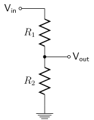
A voltage divider is two resistors in series, with different voltages applied to both ends. (That’s an oversimplification, but stick with me for a second.) Here’s what a voltage divider looks like on its own:
In the case above, the voltage at Vout is: $$ \begin{align} V_{out} = V_{in} \times \cfrac {R_2} {R_1 + R_2} \end{align} $$
The two resistors in series in the “amplifier” configuration form a voltage divider. In case that’s not clear, I’ll redraw the schematic slightly.
I hope you agree that this “amplifier” circuit is the same circuit as the one I’ve been drawing all along, only with the resistors in a slightly different position. Now we can answer the question of “What voltage at Voutput will cause the voltage at V− to reach 1V?”
Well, let’s just substitute in the values we know into the formula (5) above.
In particular, let’s use 1V for Vout in the voltage divider, which
is the point we are connecting to the - input of the op amp.
For the voltage divider alone:
$$ \begin{align} \begin{split} V_{out} = V_{in} \times \cfrac {R_2} {R_1 + R_2} \\ 1V = V_{in} \times \cfrac {50} {100 + 50} \\ 1V = V_{in} \times \cfrac {1} {3} \\ V_{in} = 3V \end{split} \end{align}$$
So a voltage of 3V applied at Vin will cause Vout in the
voltage divider.
Therefore, if our op amp is sending 3V to its output (which corresponds to
Vin on the voltage divider), the voltage divider will
result in sending 1V to the - input (labeled below as V−, which corresponds
to Vout on the voltage divider diagram above). Just to make that clear, I ran it in
a simulator and applied voltage probes to the output and to the - input:
So, when we make the two input voltages to the op amp different by raising Vinput to 1V, the op amp will note that V+ − V− is positive, and will start to swing Voutput way up, only stabilizing when V− also reaches 1V, which happens when Voutput reaches 3V. Hence, with the specific resistor values of 100k and 50k, the gain is:
$$ \begin{align} \begin{split}Gain =\left(1 + \cfrac {R_f} {R_g}\right)\\=\left(1 + \cfrac {100k} {50k}\right)\\=\left(1 + 2\right)\\=3 \end{split} \end{align} $$
As I mentioned previously, the “buffer” is just an extreme case of the amplifier; Rf is 0 Ohms and Rg is infinity. And that’s why the “amplifier” circuit can’t ever have a gain of less than 1; once you get to the point where your “amplifier” becomes a “buffer” there are no resistor values which you can plug in which will make your gain any lower.
Level 8: Impedance
Let’s recall the description of the “ideal op amp”:
An “ideal op amp” has infinite gain, infinite input impedance, zero output impedance, infinite bandwidth, and zero noise.
What does “infinite input impedance” and “zero output impedance” mean?
Well, “impedance” is the sum of any resistors and the resistive effects of capacitors/inductors on the circuit. For direct current impedance is resistance. For alternating current/audio you have to consider both the resistance from resistors and the reactance from any capacitors or inductors in the cirucit.
Infinite input impedance means that current does not flow into either input of an ideal op amp. Real op amps are not ideal and some current goes in, but not much.
Note that the op amp has zero input impedance at its inputs. If you build a
circuit such an an inverting amplifier with a resistor before the - input,
then the input impedance of the whole circuit is the resistor value, not
infinity. This means that if you connect a source to the input of an inverting
amplifier with a fairly high impedance relative to the resistor, you will change
the amount of feedback and hence the amplification! In such cases you will
want to add a buffer prior to the inverting amplifier to isolate the source’s
impedance.
Zero output impedance is a little harder to understand! The op amp will try to hold its
output at some voltage. Let’s say you have it configured as a buffer and then
connect 1V to the + input. Then the op amp will try to hold its output voltage
at 1V. The tricky part is that it will try to do this for any load you put on
it. In other words, it will try to supply the same 1V for any current you
attempt to draw.
Let’s say the output load is a 10k ohm resistor. Then the op amp will emit 1V at a current of 100 µA (because of Ohm’s Law). Similarly, if you change the output load to a 1k resistor, then the op amp will emit 1V at 1 mA.
Again, real op amps are not ideal, and of course the current a real op amp can emit is not infinite!
Level 9: How the Inverters Work
As we’ve seen, the buffer circuit is just a special case of the amplifier circuit, and as I hinted when I first mentioned the resistor values in the “inverting amplifier” configuration, the same thing is true of the inverter and the inverting amplifier; the inverter is just a special case of the inverting amplifier. Namely, it’s what you get when both resistors have the same value. But it’s not the same special case.
To cut to the chase, the formula for the gain of an inverter is:
$$ \begin{align} V_{output} = -V_{input} \times \cfrac {R_f} {R_{input}} \end{align} $$
As with the amplifier, it is worth memorizing this formula. Just like before, we will look at why this formula is true.
Comparison with Amplifiers
With a (non-inverting) amplifier if both resistors have the same value then you get a gain of 2. To get unity gain in the non-inverting amplifier case (a buffer), you use one “resistor” of 0 Ohms (a wire) in the feedback loop and one “resistor” of infinity ohms (no connection whatsoever) going to ground. With an inverting configuration you get unity gain (a plain inverter) if both resistors have the same value. Clearly, these two don’t work in quite the same way! The differences don’t end with the formula, either.
Let’s recall what the inverter circuit looks like:
These circuits, despite their superficial similarity, are just different.
| Amplifier |
Inverting Amplifier |
|---|---|
Vinput goes directly to + input |
Vinput goes to - input via a resisitor |
| The “other” op amp input (V−, the one not connected to Vinput) is connected to the output. | The “other” input is connected to ground. V+ will always be 0V, and hence V− will be held at 0V by the feedback loop. |
| The feedback and the input are connected to two different op amp inputs | The feedback and the input are connected to the same op amp input (-) |
| $$V_{output} = V_{input}\left(1 +\cfrac {R_f} {R_g} \right) $$ | $$V_{output} = -V_{input}\cfrac {R_f} {R_{input}}$$ |
The question is, why are they different? We have already examined why the non-inverting amplifier behaves the way it does. Let’s take a deeper look at the inverting case.
Why the Inverters Invert
The op amp will emit whatever voltage is required to hold the difference between
the two inputs to 0, but one input is always 0V, being connected directly to
ground! Therefore, the op amp must
adjust its output so that both inputs will be held at 0V. The phrase commonly
used to describe this is that the - input is “held to a virtual ground,”
because there is not a direct connection to ground, but the op amp will ensure,
via feedback, that V− cannot ever be anything but 0V. (Saying “cannot ever
be anything but 0V,” however, is not the same as saying “shorted to ground.” If
you were to short the - input to ground then
the circuit would stop working.)
In the discussion that follows it will be helpful if we add some labels to the schematic:
If the voltage at the input of the circuit (the far left-hand side, above), which
I’ll call Vinput, goes high, then it stands to reason that this will tend to
raise the voltage at the - input of the op amp, which I’ll call V−, even
though there is a resistor in between them. This is going
to cause the difference between the two inputs, V+ − V−, to be negative, because
V+ is fixed at ground, 0V, and therefore the difference is negative. So the op amp
will put out a large negative voltage at its output, and this will have the
effect of lowering V− back down to 0 (due to the feedback wire, through the
resistor) and bringing everything back into equilibrium. So we can see how this
configuration is “inverting,” at least as far
as the sign of the gain is concerned.
Why the Inverter Uses a Different Formula for Its Gain
But why is the formula different? Why does using the same resistor value for both resistors result in (negative) unity gain for the inverting case but result in a gain of 2 for the (non-inverting) amplifier case? The two resistors in series are a voltage divider in both cases, but they have different voltages being applied to them. In the case of an inverting amplifier, however, the 0V is at the middle of the voltage divider (the node we called Vout when we discussed voltage dividers), not at the bottom.
We are changing both ends of the voltage divider at the same time, one via
Vinput and one via the feedback loop, so we can’t use the “simple” voltage
divider formula to know calculate the middle value — which we know anyway,
since it’s held at 0V. It will turn out, in the next Level, that there are
additional reasons not to analyze this circuit as a simple voltage divider.
Instead the easiest way to understand what is happening in this circuit is to
consider
Kirchhoff’s Current Law,
which says that the current going into and out of any point in
a circuit must sum to 0. Let’s examine the point at the - input to the op amp,
where we are measuring V−.
In this case the analysis is pretty simple! For an “ideal” op amp, the amount of current going into the op amp itself is 0 amps. (Remember, that’s what the “infinite input impedance” part of the description of an ideal op amp means.) Therefore, the amount of current coming from the input, iinput, must be exactly the same as the amount going to the output, ifeedback. (Don’t read too much into the direction of current flow here; pick a direction and then you can set the sign of the current positive or negative as needed. The important point is that the current is the same across both wires.)
The currents are the same, the resistors are the same, and we know one voltage. Therefore, both voltages, per Ohm’s Law, must also be the same magnitude! Only the signs are different. Any voltage we apply at Vinput must drop to 0V at V− due to:
- the fact that V+ is directly connected to ground and
- the feedback mechanism which makes the op amp hold its two inputs to the same value
Therefore, if we apply 1V to Vinput then it will drop to 0V at V−. Voutput will be set to whatever voltage is required to set V− to 0V. What voltage is that? Because iinput and ifeedback are the same, and because the two resistor values are the same, Ohm’s Law tells us Vinput and Voutput must be the same, except that the sign flips because the voltage must drop in the same direction, and in the case of the difference between V− and Voutput the voltage is going down from 0V. So for Vinput = 1V, Voutput must equal -1V.
Comparing and Contrasting the Buffer and Inverter Circuits
This may be clear by now, but just to review:
The way buffer circuit works is that you send some voltage to Vinput,
which is directly connected via a wire to the + input of the op amp. So
the + input is at the same voltage as Vinput, and there is a feedback
loop connecting the output of the op amp to its - input. When Vinput is
higher than the output/the - input, the op amp notices that the difference
between its two inputs is positive swings the output higher
until both the + input and the output are at the same level, at which point
the feedback tends to hold the output steady. When Vinput is lower than the
output, the op amp notices that the difference between its two inputs is
negative and swings the output lower until both the + input and the
output are at the same level, at which point the feedback tends to hold the
output steady.
The way an inverter circuit works is that the + input of the op amp is directly
connected to ground and can never be at any level other than 0V. When you send
some voltage to Vinput, if the voltage is greater than 0V then the op amp
notices that the difference between its two inputs is negative and must emit a
negative voltage to counteract the positive voltage at its - input via the
feedback loop, which is connected, via a resistor to the same - op amp input as
Vinput, also via a resistor. If the voltage is less than 0V then the op amp
notices that the difference between its two inputs is positive and must emit a
positive voltage to counteract the negative voltage at its - input via the
feedback loop.
Level 10: Passive and Active Mixers
Thus far we have examined why the non-inverting and inverting amplifier circuits have different formulas, but, as I’ve hinted, that’s not the end of the story. Let’s change the number of inputs from one to two.
Non-inverting, Passive Mixer
Here’s the non-inverting configuration:
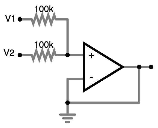
This is a passive audio mixer followed by a buffer. Why use the resistors at all? Because if we connect one signal at 1V to one input and one signal at ground to the other input, we don’t want to just short the first voltage source to ground. The sending audio equipment will probably not be built to withstand that!
This actually works, but it has a number of problems. If you build the mks x es.EDU Mixer kit you get to explore these problems, but I will explain them here. All of them stem from the fact that the resistors between V1, V+, and V2 are a voltage divider – or, at least, they are when there is a connection to V2 at all, which may or may not be the case with an audio mixer!
- If you connect 1V to V1 only (and nothing whatsoever to V2), then the voltage at V+ is 1V. So far, so good! The resistor connected at V2 isn’t involved at all with nothing connected to V2.
- If you then connect 0V to V2, then the voltage at V+ will drop to 0.5V, because now the second resistor is in the circuit and the two resistors form a voltage divider. This will be unexpected for an audio engineer! It is not generally the case that plugging in a silent signal reduces other signals.
- You might replace the two 100k resistors with potentiometers so that the engineer can set audio levels for both inputs. This works, but they will find that adjusting the level of the input at V1 also affects the level of V2, again due to the voltage divider. This will again be surpising to most audio engineers, and massively inconvenient if you’re mixing 32 inputs instead of 2.
So, maybe not the best design.
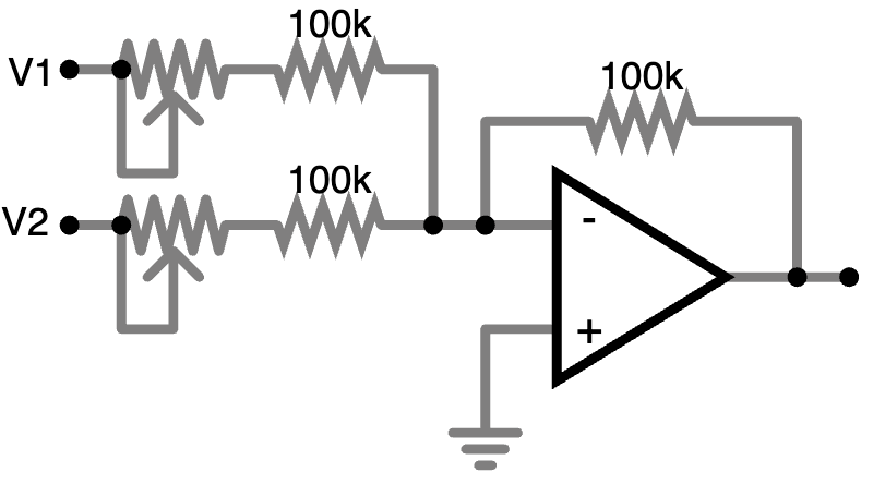
Inverting, Active Mixer
Instead, let’s try grafting the same “passive” mixer onto an op amp in an inverting amplifier configuration and see what we end up with?
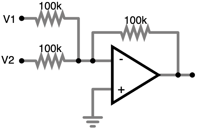
This is something else entirely! The - input, instead of just being at
whatever voltage comes from the two “V” inputs, is now held at ground by the
inverting op amp. How much voltage is required to hold the - input at ground?
Precisely the same amount that the “V” inputs are supplying. Let’s examine the
deficiencies of the “Passive/Non-inverting” mixer and compare:
- If you connect 1V to V1 only (and nothing whatsoever to V2), then the op amp must emit a voltage of -1V to counteract the input and reduce the voltage at V− to 0V. So far, so good; we’re inverting!
- If you then connect 0V to V2, no current flows through the resistor connected to V2, because V− is also held to ground. There is no voltage difference across the resistor and hence no voltage flows. The feedback voltage is still set to -1 V just like before to counteract the voltage from V1.
- You can’t “replace” the two resistors with potentiometers, because potentiometers can be set to 0 ohms, and you need at least 100k (in the case pictured) to balance the resistor on the feedback loop. However, you can add a potentiometer in series with a 100k resistor:
It’s probably worth talking about how I am choosing these resistor values. The exact resistance of any resistor in the circuit is not as important as its relationship to the values of other resistors. By equation (8) we know that the gain of an inverting amplifier is governed by the ratio between the feedback resistor and the input resistance. So in principal we could use 100 ohm or 100M ohm resistors in the circuit and it would be fine.
Well, sort of: It turns out that using 100 ohms is asking the op amp to push a lot of current, which is not so great for its lifespan, and also has effects which show up as noise in the output. Using 100M ohms is also signing up for a lot of noise, for different reasons. The values used in this article are, to be honest, just copied from other examples, such as the mki x es.EDU schematics, which I have observed work well. But if all you have on hand are a bunch of 68k ohms resistors, you’ll be fine.
Conclusion
In this article I have focused on some specific examples of useful circuits you can build with an op amp. However, I want to reiterate that these are not the only useful circuits you can build, and you should expect to see other examples as you review schematics “in the real world.” Wikipedia has a list with more examples, and there are even more to be found in the world. It’s amazing what you can do with a simple, 2 input IC and a few passive parts!
I will also reiterate that if you’ve read this far, then you are certainly on my A-list of favorite people in the world, and you should feel free to reach out if something doesn’t make sense to you or if I’ve made any obvious errors you’d like to point out!
Next time we will return to synth construction and build the VCO on a PC board.
“I have made this longer than usual because I have not had time to make it shorter.”
-Blaise Pascal
Glossary
- Closed loop gain
- We’ve just been calling this the “gain” so far in this article. The closed loop gain is the gain of an entire op amp circuit when wired in a feedback (that’s the “closed loop”) configuration. For example, if you use two resistors of the same value in an amplifier configuration, then the op amp has a closed loop gain of 2.
- Impedance
- Impedance is just resistance in a DC circuit and the sum of resistance plus reactance from capacitors, inductors, and the like in an AC or audio circuit. However, we tend to talk about a circuit’s “input impedance” and “output impedance,” and although the term “impedance” means the same thing in these contexts, saying “the sum of resistance and reactance” may not be the best mental model for understanding input and ouput impedance. I find it helpful to think of a circuit’s input impedance as “how much current can flow into the circuit?” Likewise, I think of a circuit’s output impedance as “How much current can the circuit supply?” These questions are of course the same as saying “the sum of resistance and reactance,” per Ohm’s Law, but I find them to be a more helpful model.
- Open loop gain
- The open loop gain is the gain of the op amp by itself, without anything connected to it. It’s typically a very large value in the neighborhood of 100,000
- Virtual ground
-
When an op amp is in an inverting configuration with the
+input tied directly to ground, we say that the-input is “held to a virtual ground.” This is not the same thing as being connected directly to ground with a wire! If you connect the-input directly to ground with a wire, then your inverting amplifier will cease to function. The reason is that then the difference between the two inputs will always be 0 − 0 = 0, so there will never be any voltage output from the op amp. In order for an inverting amplifier to function, the op amp needs to detect the-input trying to increase in voltage so that it can note a difference between its two inputs and emit a voltage at the output to force it back down to 0V.
Resources
Instructions
- mki x es.EDU VCO User Manual This manual has a section discussing how the “buffer” configuration works, and it also (in a separate context from op amps) explains voltage dividers.
- mki x es.EDU Mixer User Manual This manual has experiments with and explanation of different op amp configurations in the context of building a mixer, and includes discussion of passive vs. active mixers using both non-inverting (“buffer”) and inverting configurations.
Videos
If you prefer to learn from a video lecture, here’s a good one which covers similar material to the one in this post
- EEVblog #600 - OpAmps Tutorial - What is an Operational Amplifier?, by EEVblog (49:31)
If you’re even passingly interested in analog synthezier electronics then all of Prof. Aaron Lanterman’s videos are probably worth your time, but these three are particularly relevant to this topic
- 3 Op Amp Circuits All Electrical & Computer Engineers Should Know by Heart (ECE Design Fundamentals), by Prof. Aaron Lanterman (14:11)
- Passive Signal Summing/Mixing, Using Only Resistors (ECE Design Fundamentals, Georgia Tech course), by Prof. Aaron Lanterman (19:13)
- Active Signal Summing/Mixing, Using Op Amps in Inverting Configurations (ECE Design Fundamentals), by Prof. Aaron Lanterman (12:53)