Building a Synthesizer, 5
Building the VCO
- Introduction: The World of DIY Synthesizers
- 1: The mki x es.EDU DIY System
- 2: Building the Power Supply
- 3: Breadboarding the VCO
- 4: A Gentle Introduction to Op Amps
- 5: Building the VCO
- 6: The Logic Circuits Model of Computation
- 7: Building the Mixer
- 8: Building the Envelope Generator
- 9: A Field Guide to Oscillators
- 10: Building the VCA
- 11: Debugging Circuits and Software Debugging
- 12: Breadboarding the VCF
- 13: Building the VCF
- 14: Building the Sequencer
- Glossary and Electrical Connections
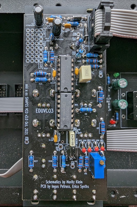
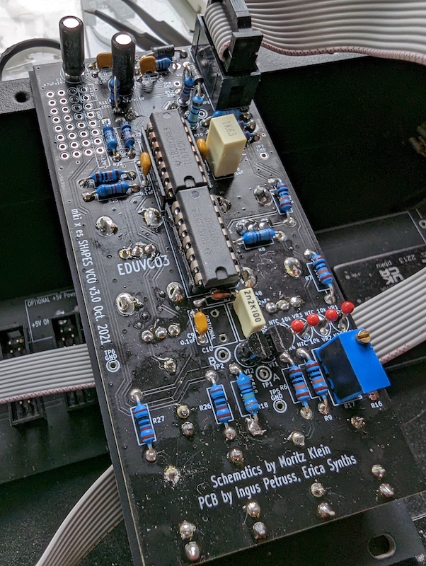
Actually building the PC board incarnation of the VCO was quite a bit easier than getting it to work on the breadboard. Really there was nothing tricky about it; I just soldered it together and it worked well the first time. I don’t really remember how long it took; I’m thinking 2-3 hours? It was certainly much easier to solder than the power supply, where the large ground traces made getting the solder joints hot enough difficult.
This once again reinforces my feeling that I made the right decision getting the mki x es.EDU kits instead of some of the other synthesizer kits on the market. The emphasis on breadboarding allows me to make and fix mistakes, and that’s the best way to learn. When you connect components to labeled holes on a PC board, well, there’s not a ton of opportunity to screw things up.
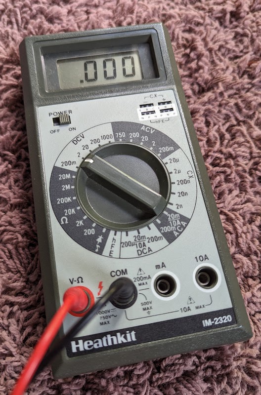
When I was in high school I occasionally built Heathkit electronics kits. I still have my Heathkit DMM that I built decades ago. Their motto was, “We won’t let you fail.” Now I am thinking it would have been better if they did let me fail, just a little!
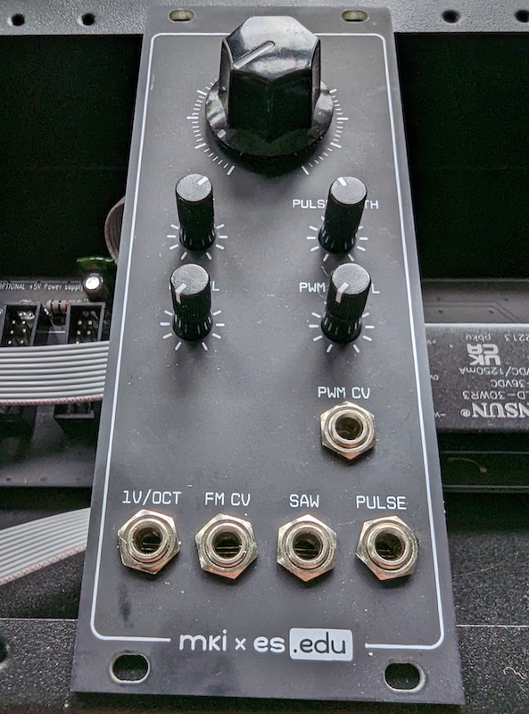
Differences Between the Breadboarded VCO and the PC Board Version
The PC board version has some extra components which are not used when you build the VCO on the breadboard. These are mostly discussed in the instructions in the section entitled “Module Assembly Appendix,” so I’ll refer you there for an explanation of what they do.
The is a component which is added to the PC board version and which is not mentioned in the “Module Assembly Appendix.” The PC board version adds 1k resistors in front of the two output jacks. Presumably this is to protect the circuit if the output is accidentally shorted to ground while plugging in a patch cable. Putting a 1k resistor here ensures that there is always some resistance on the output, even if the patch cable momentarily joins the output with ground while plugging it in/out
Tuning
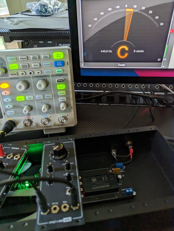
Nothing takes the romance out of analog synthesizers faster than tuning. When you play a note, let’s say middle C, on a keyboard, you would ideally like the VCO to oscillate at a corresponding value of 261.63 Hz. Many things have to be set correctly for this to happen!
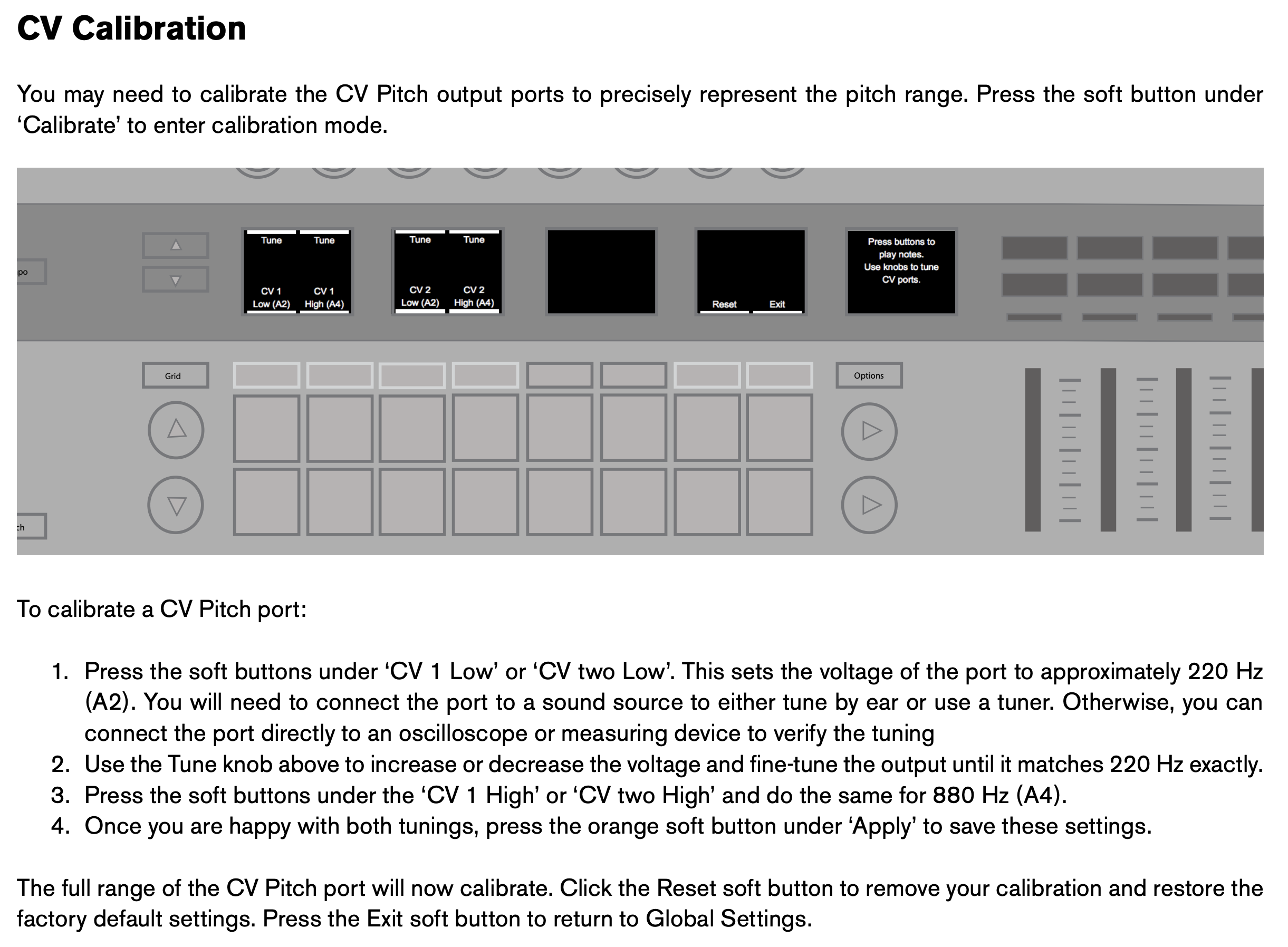
Let’s start with the keyboard: It will emit a pitch control voltage when you play a key, but will it be the “correct” voltage for the modules you use? My keyboard has a “CV Calibration” feature which allows you to change the pitch CV emitted when you press a key.
So my first task was to connect the keyboard’s pitch CV output to a voltmeter and adjust this signal to the expected values. What are those? this list seems fairly standard. (The list of voltages currently on Wikipedia sets 0V = A instead of C. There has been disagreement on which note 0V should correspond to over the years, but for Eurorack you’ll want it to be C.) I do not recommend doing this by connecting to a sound device and tuning it by ear, as the instructions suggest, because the sound device itself might be out of tune. One thing at a time!
Unfortunately, I found a firmware bug while doing this! Adjusting the “CV 1 Low” and “CV 1 High” dials didn’t change the pitch or produce any visual indication that they were doing anything. I eventually figured out that although they were adjusting the pitch I couldn’t hear the change until I pressed another button to change to the other control. I guess I will report that to Novation. At any rate, I was eventually able to get the output voltage correct.
That sorted, I could then connect the keyboard’s pitch CV to the VCO’s “1V/oct” input and tune the VCO. There’s a video of Moritz Klein tuning the breadboarded version of an early version of this project which you can watch to see the project. I do think he makes this process seem a bit easier than it actually is, though!
When you’re first tuning the VCO, it might be way out of tune. Here are some tips for tuning the VCO:
- Warm up the VCO by powering it on for 15 minutes or so before you start
- Try to avoid handling the module too much (although it’s difficult to avoid!), and especially don’t touch the temperature-sensitive components such as the thermistors and transistors
- Like Moritz does in the video, I used a hardware sequencer to emit an alternating pitch and used a plugin tuner. But I also connected a software instrument so that I would have an audio pitch reference as well.
- The first time you tune, start with a narrow interval such as one octave. Then expand the interval. Later you can go directly to five octaves or whatever.
When you are tuning a mki x es.EDU module which is not on a breadboard, the 1k precision trimmer (“offset”) and the coarse/fine pots are on opposite sides of the module! So the process of tuning involves a lot of handling the module as you flip it back and forth. This seems unnecessary and it’s probably my biggest complaint about the VCO. Why not make the trimpot accessible through the front of the module?
Also, while you’re handling the module, be careful not to touch the line of 4 thermistors, which are right next to the trimpot! They are there to keep the pitch stable even when the operating temperature of the whole module changes (due, perhaps, to a change in outside temperature or internal heating of a nearby power supply). Touching one will throw the pitch off!
I found having both a software instrument playing an audio pitch reference as well as a tuner helpful when tuning for a couple of reasons. First, my tuner only reports the note name, not the octave. When I was first tuning the VCO I wasn’t sure it was even playing the correct octave! Second, a tuner will tend to jump between the “actual” note that you’re playing (say, a C) and its relative fifth (G, in this case). Having an audio reference makes it easier to distinguish these, and it’s very easy to do when your keyboard can emit both MIDI and CV at the same time.
Some modern analog synthesizers have an auto-tune feature, but the mki x es.EDU VCO unfortunately does not have this nicety.
Instructions Errata
One kind of funny omission from the instructions: For whatever reason, one of the resistors, R11, was never shown assembled in the photos. Looking at the schematic it’s certainly needed, and an appropriate resistor is included with the kit.
Test Point Voltages
Someone was asking for this data, so here are the voltages I measured at the various test points on the PCB with the completed kit.
Before Tuning
Before I tuned the oscillator, I measured the voltage at test points A-D.
For test points A-C, I moved the large coarse tuning potentiometer when taking measurements. For test point D, I moved the PWM Width potentiometer when taking measurements. In all cases I took these measurements without connecting any kind of external CV signal, which might have changed the “DC” signals into something else entirely.
| A | B | C | D | |
|---|---|---|---|---|
| Signal type* | DC | Saw | Saw | DC |
| Pot at 0% | 0.37V | 3Vpp, 8.92 Hz | 3Vpp, 8.92 Hz | -1.39V |
| Pot at 50% | 0.46V | 3Vpp, 273 Hz | 3Vpp, 273 Hz | 0.08V |
| Pot at 100% | 0.52V | 3Vpp, 3905 Hz | 3Vpp, 3905 Hz | 1.39V |
*The signal type when no CVs are connected to the input jacks.
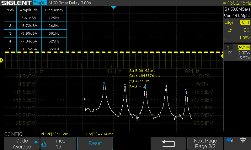
After Tuning
I also measured the voltage out of the oscillator from the PWM jack after tuning and with a “C3” (one octave below middle C) CV voltage on the 1V/Oct jack. This is an FFT of the square wave which you can see in yellow. It’s cool because you can see the harmonics in the FFT chart.
What’s Next?
In keeping with the semirandom nature of the posts in this series, I will have a few things to say about alternate models of computation. Stay tuned!
Resources
Instructions
Community
Product Pages
Simulation
- The full VCO (as breadboarded; this is missing a few components not on the breadboard such as thermistors and output protection resistors)
Videos
- Introducing the mki x es.edu DIY VCO kit by Moritz Klein (7:23). This is a super-short overview with a demo of the full system.
- Erica Synths .EDU VCO - Building, tuning, playing by Synth Diy Guy (17:53)