Building a Synthesizer, 12
Breadboarding the VCF
- Introduction: The World of DIY Synthesizers
- 1: The mki x es.EDU DIY System
- 2: Building the Power Supply
- 3: Breadboarding the VCO
- 4: A Gentle Introduction to Op Amps
- 5: Building the VCO
- 6: The Logic Circuits Model of Computation
- 7: Building the Mixer
- 8: Building the Envelope Generator
- 9: A Field Guide to Oscillators
- 10: Building the VCA
- 11: Debugging Circuits and Software Debugging
- 12: Breadboarding the VCF
- 13: Building the VCF
- 14: Building the Sequencer
- Glossary and Electrical Connections
Nearly all synthesizers have a filter of some kind. There are many different filter designs. Even a phrase like “the Moog ladder filter” can mean many different actual circuits. Differing filter designs can have as much to do with the character of how a synth sounds as different oscillator shapes.
A VCF stands for a “Voltage Controlled Filter,” which is similar to a regular equalizer filter except that it can be voltage controlled, which means that we can use an Envelope Generator or a Low Frequency Oscillator to vary the parameters of the filter (such as cutoff or resonance) as a note plays.
Moritz Klein’s goal when designing the mki x es.EDU VCF was to make a “classic sounding” filter with a very simple design. And when you think about how simple a low-pass filter can be – just a resistor and a capacitor, this feels like it should be possible.
Breadboarding the Filter
One really minor difficulty I had when breadboarding these was figuring out which component was which, e.g., which jack was “input” and which was “output.” Here’s the schematic, which is clear enough:
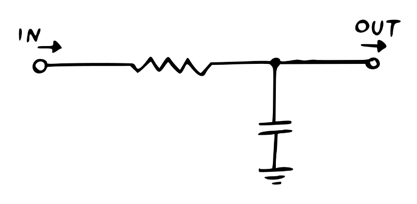
However, the breadboard layout is quite a bit less clear, and the jacks are for whatever reason never labeled in the manual. Quick, which jack is input?
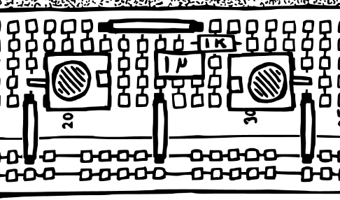
(It’s the one on the right.)
This becomes considerably harder when we start using seven op amps split across two different ICs!
Passive Filter
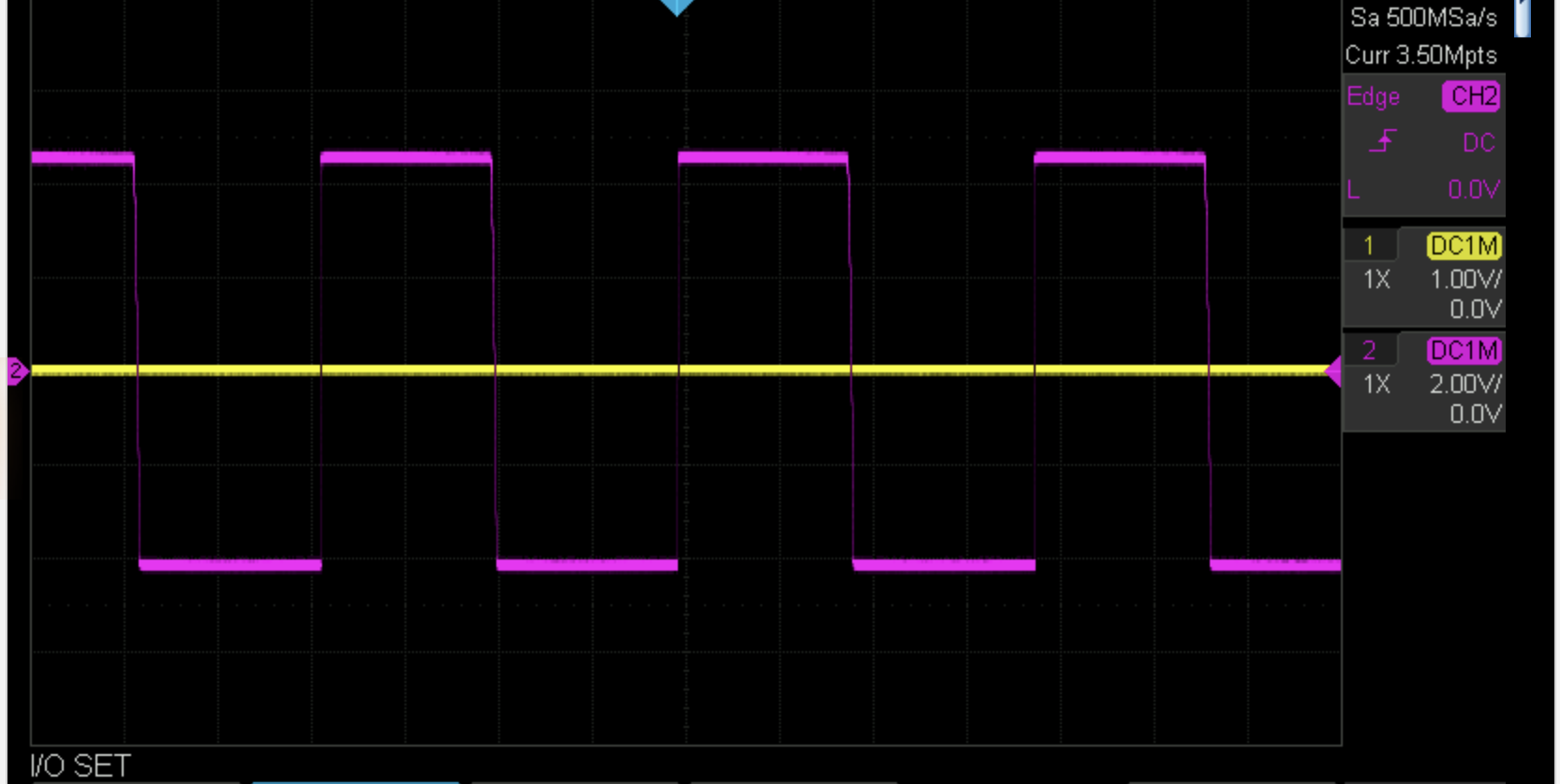
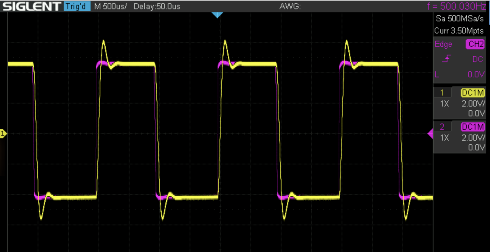
Anyway, here’s the square wave I used as the input to the filter for my testing. You’ll soon see why I need to show this by itself first.
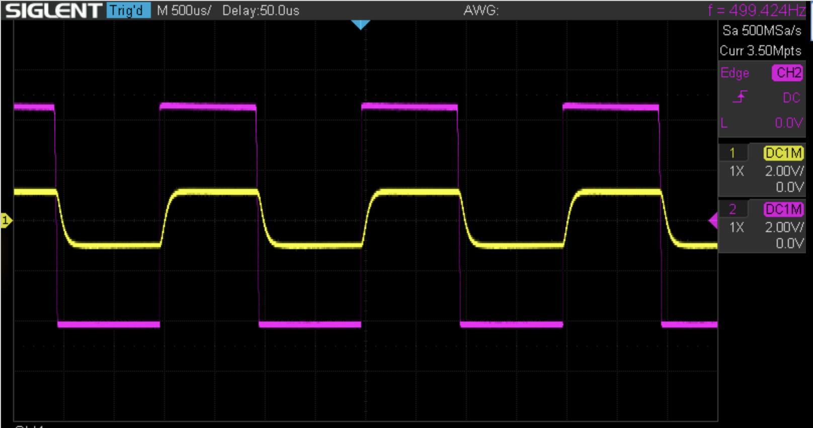
First we build a passive, first order filter using just a resistor and a capacitor. This does an OK job at filtering the output, but note that it also distorts the input signal as well, because the resistor and capacitor add impedance to the input side of the circuit, since there is no isolation between the filter and the input:
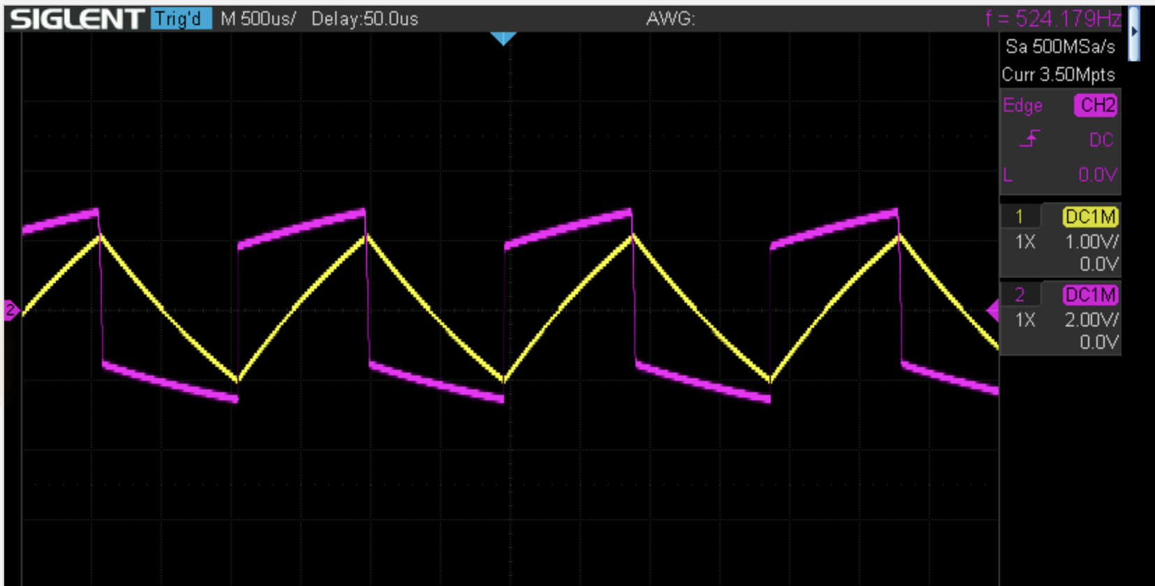
The purple trace above is the input square wave (distorted due to the passive circuit here), and the output of the filter is the yellow trace.
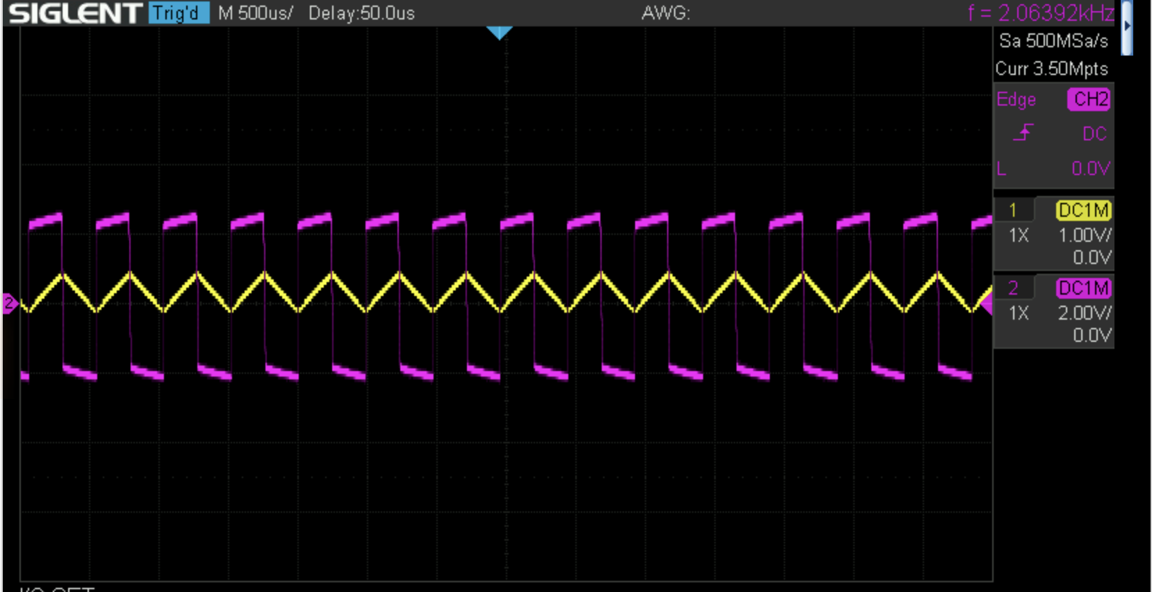
The filter doesn’t just reshape the wave; it also reduces the output at higher input frequencies. Above I’m using a 500 Hz input; here’s with a 2 kHz input.
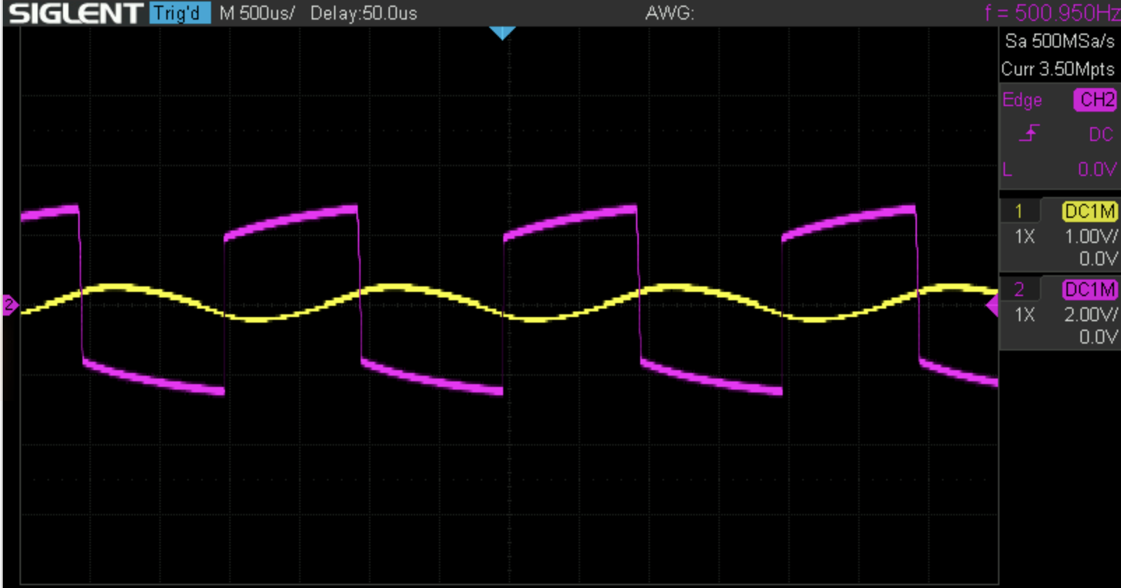
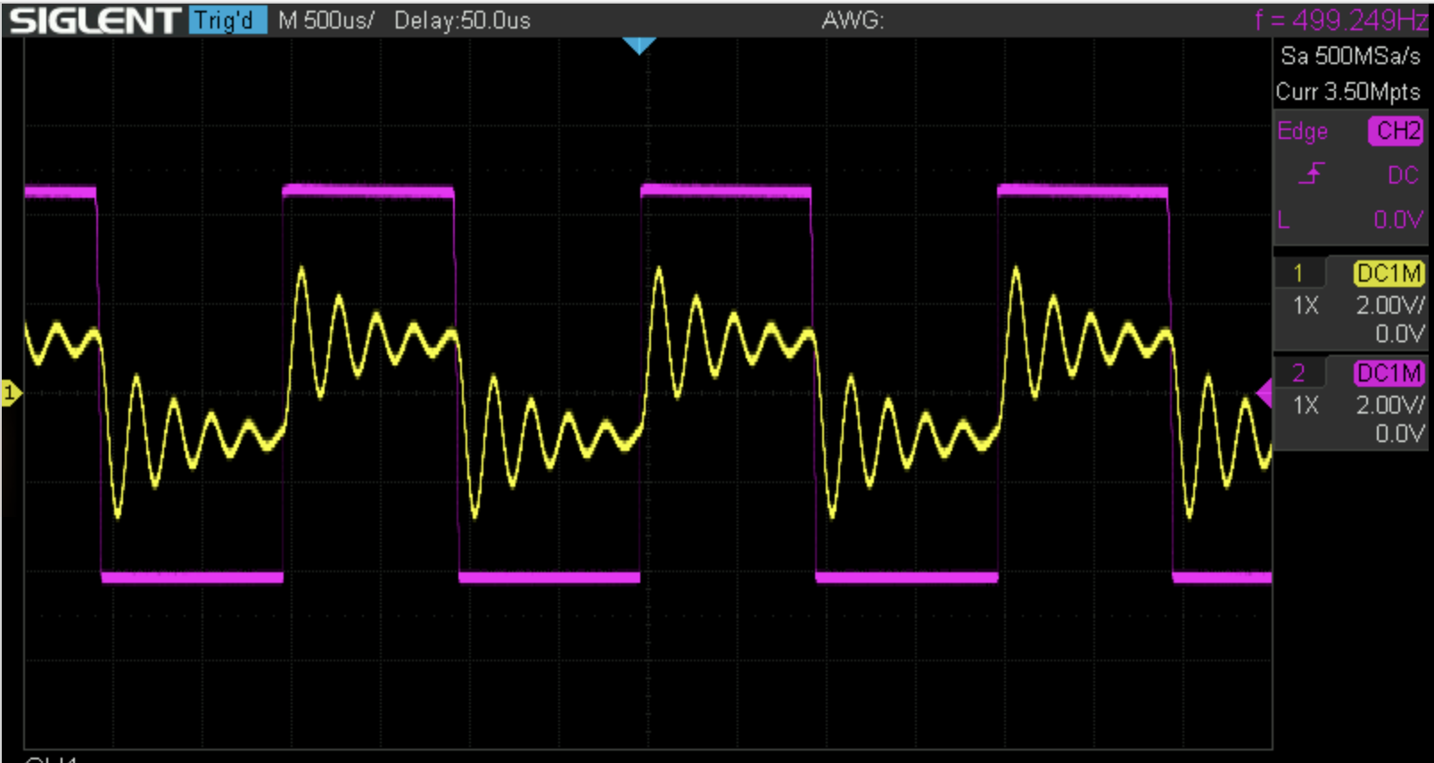
Second Order Passive Filter
Then we add a second resistor and capacitor to make a second order filter. The output is much more like a sine wave with the second order filter. However, the input is even more distorted.
Active Filter
Next we build the active filter. Here’s the schematic:
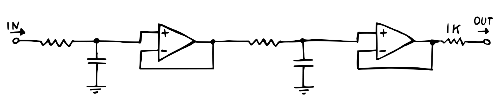
When I first build this filter, it didn’t work. I got no output at all. After some tracing, I finally noticed that we were supposed to replace the 1 µ capacitors from the passive filter with 1 n capacitors for the active filter. Unlike the real capacitors, which are visually very distinct, the “1 µ” and “1 n” are just very similar looking white blocks in the breadboard drawings, and the schematic immediately above omits their values altogether!
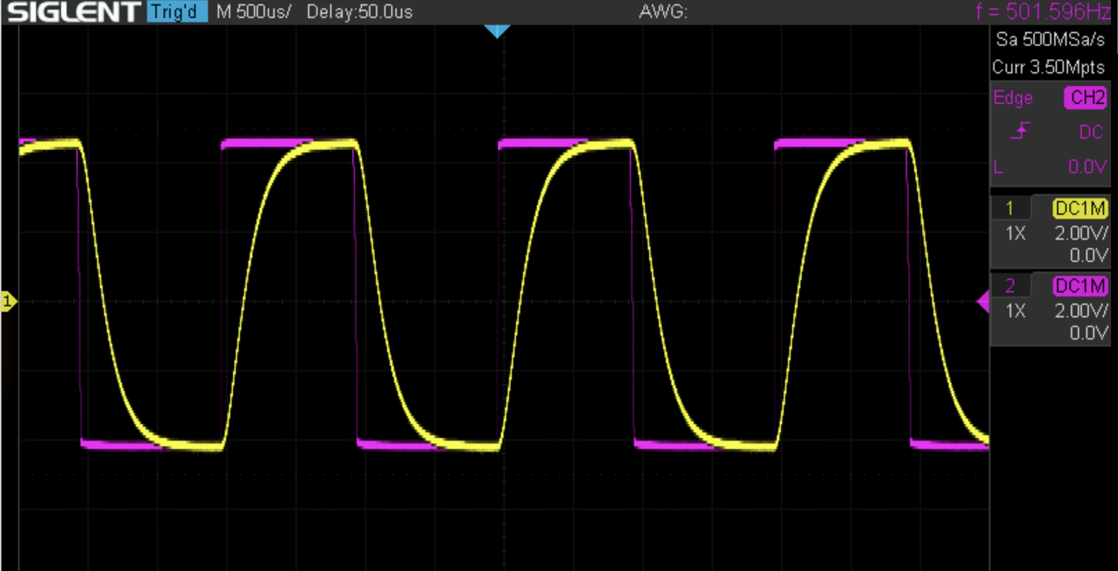
Anyway, with that sorted, I then had a respectable looking low-pass filter:
Adding Resonance
Next we make the filter resonant. We do this by feeding the output of the filter back into the first capacitor, replacing its connection to ground with the filter’s output.
In the instructions and in his videos, Moritz notes that this “is basically just the filter itself swinging at its set cutoff frequency in addition and reaction to the oscillation it’s supposed to be filtering.” That’s correct, but it’s only part of the story. In addition to the filter “overreact[ing] to any sudden change in voltage at its input,” the filter also introduces a delay in the signal as it passes through the filter and then gets partially routed back into the input of the filter. The portion of the output which is fed back into the filter circuit is out of phase with the input. Both the delay/phasing and the amplification are responsible for the characteristic sound of the resonance.
Adding the Diode Ladder
We want to make the filter adjustable using control voltage. The first step is to make it adjustable at all. This kit solves that problem using diodes as “voltage controlled resistors.” I won’t bother explaining the theory here as that is very well covered in the manual, which I encourage you to read if this project is at all interesting to you. The manuals for the mki x es.EDU DIY kits are (really) great reading.
Adding the Output Stage
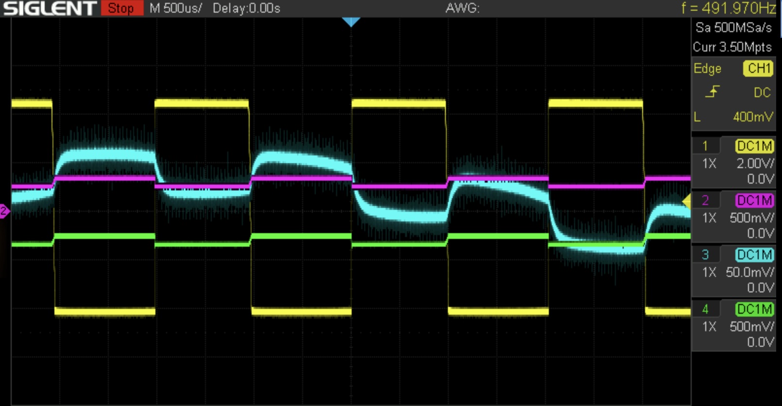
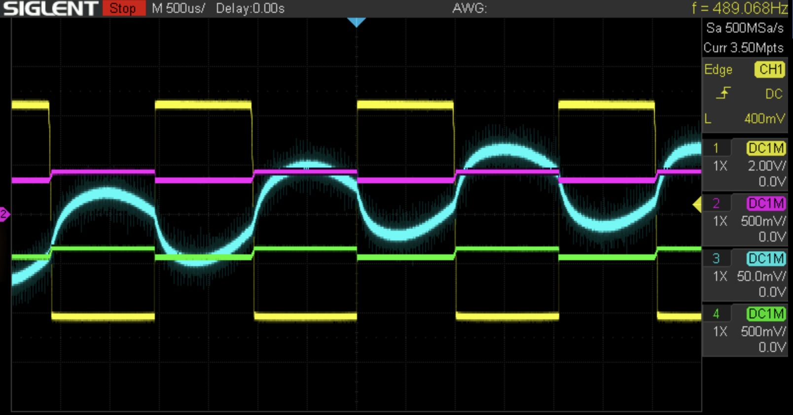
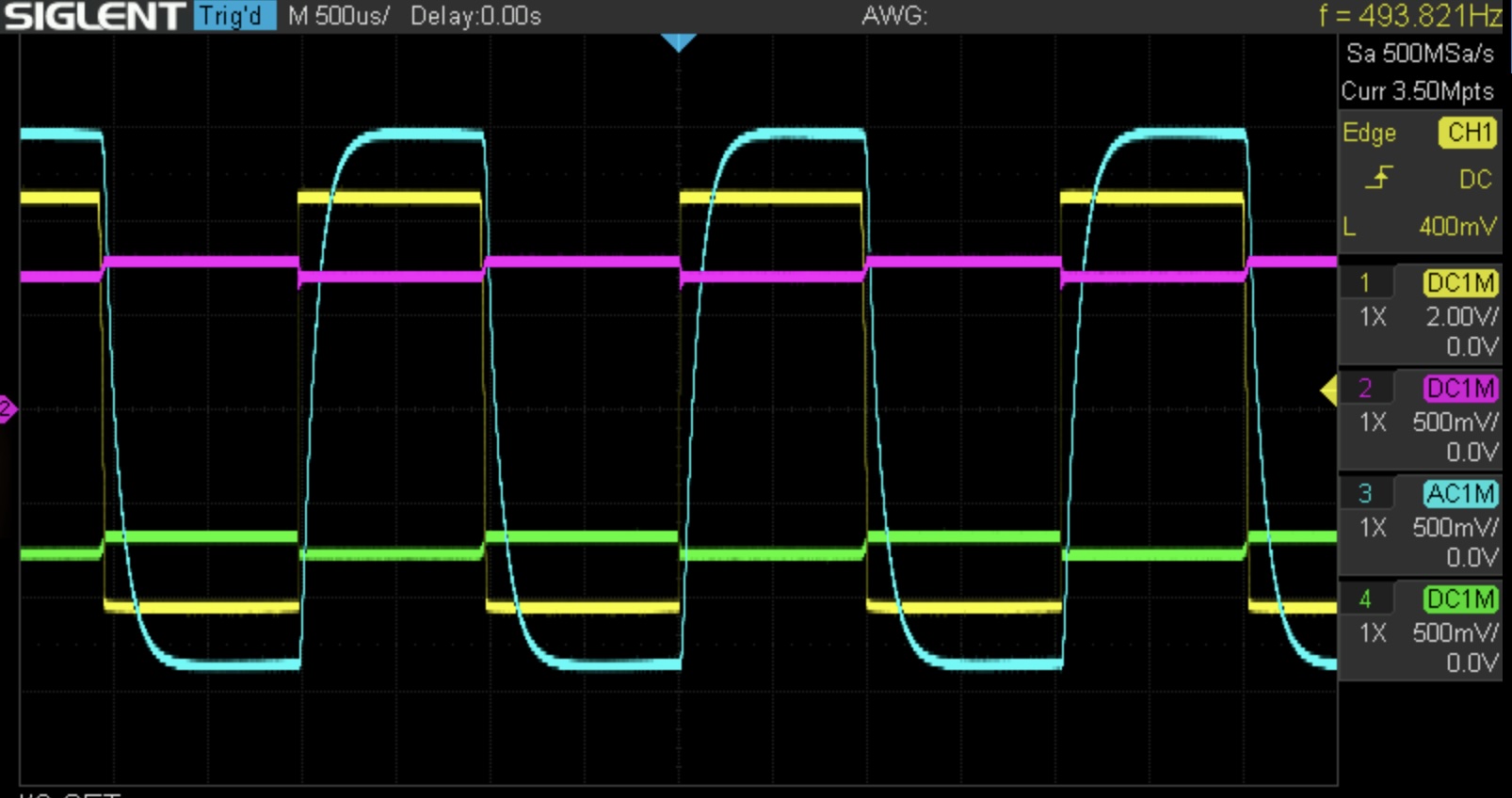
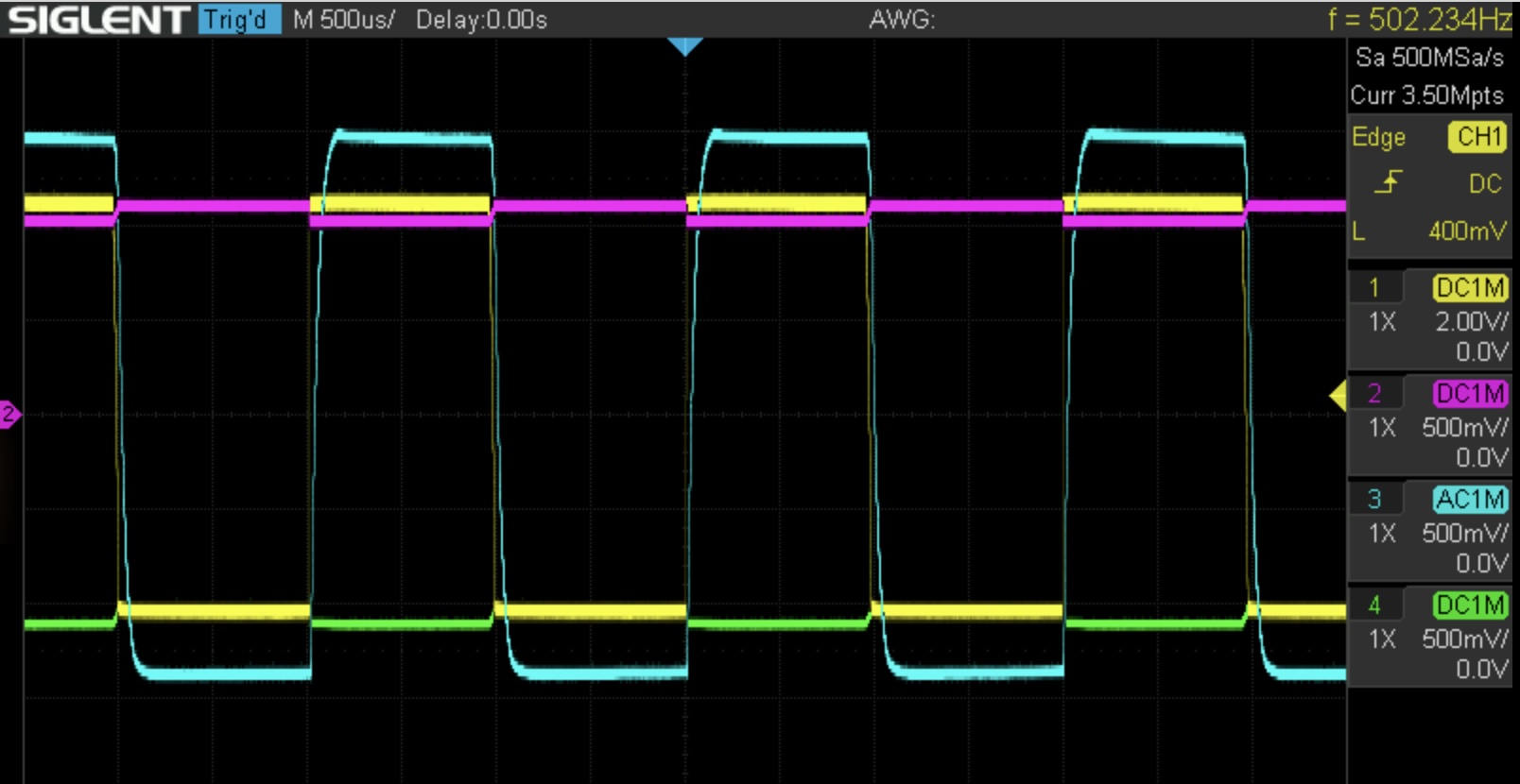
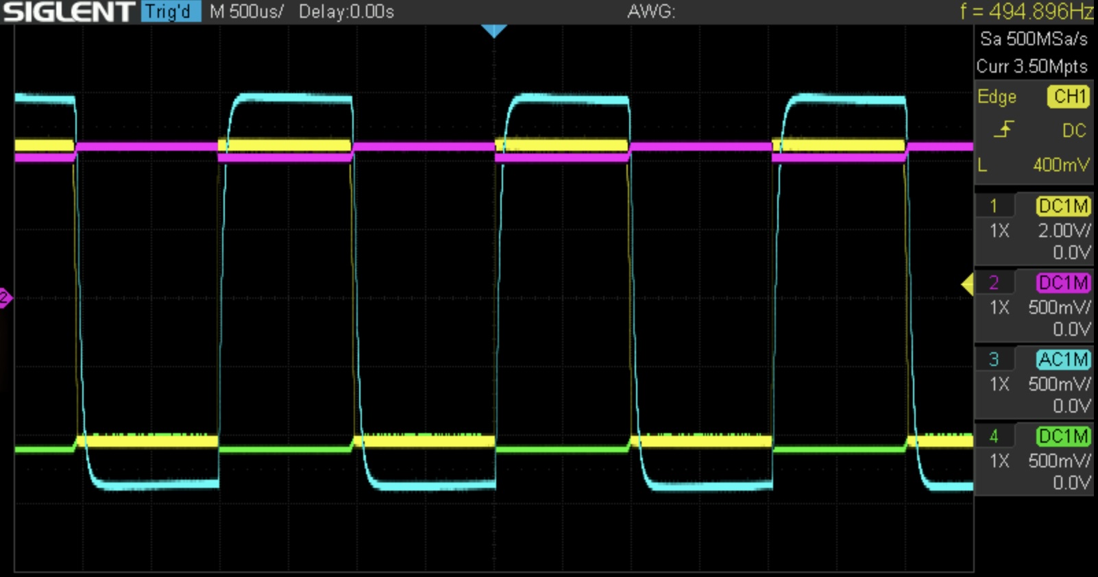
In the images which follow, the input square wave is in yellow, the top and bottom of the diode ladder are in purple and green, and the output is in cyan.
Some things to note here. First, the scaling is a bit deceptive. The input signal is much hotter than the rest of the traces (note its vertical scaling is 2V/div).
The output signal varies quite a bit in amplitude depending on where the filter cutoff is set, which isn’t ideal. We will fix that in the next section.
There’s a low-frequency noise, probably 60 Hz, in the output. I blame this on the noisy breadboard and low output level.
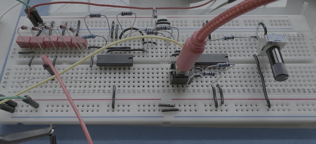
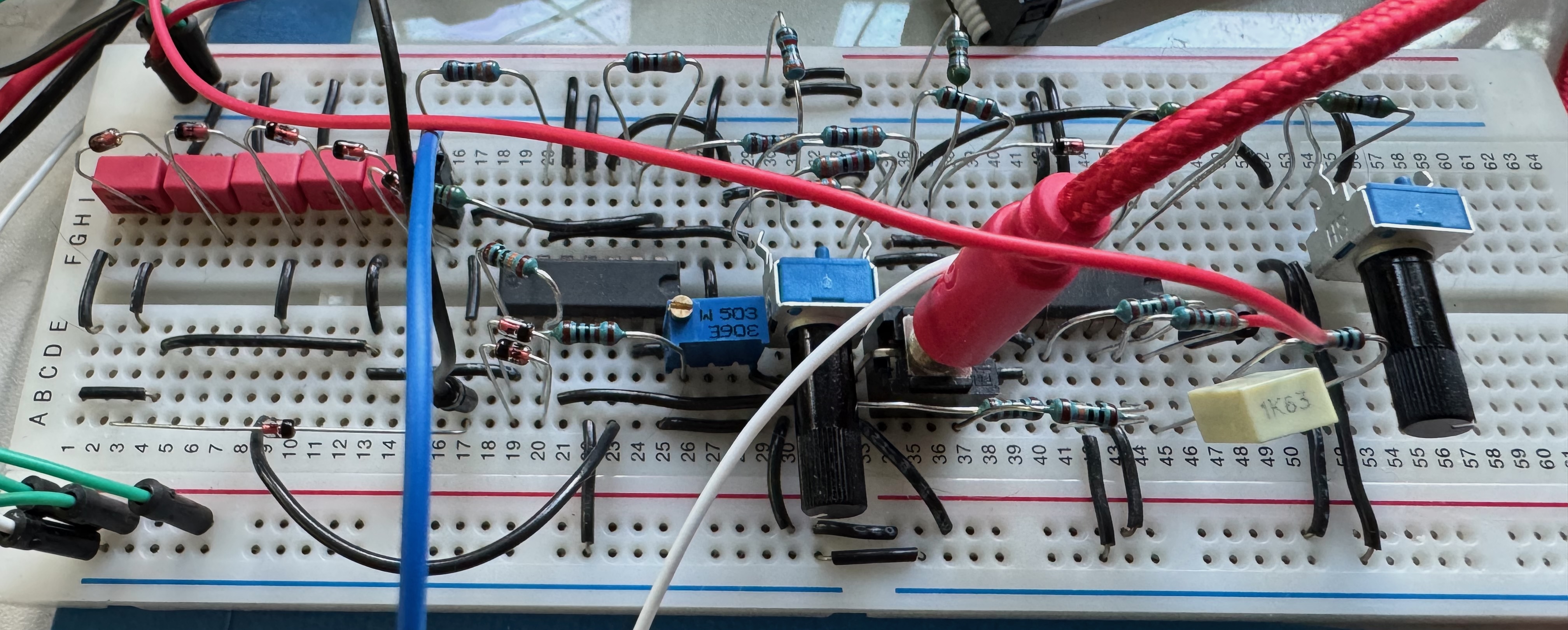
This build took me quite a while to debug. At first I found that a couple of wires were in the wrong breadboard sockets, and then after a considerable amount of troubleshooting I found a couple of resistor leads which contacted each other due to “leaning” on the breadboard. Which is, frankly, an easy mistake to make:
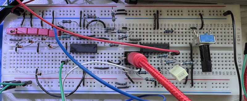
Still, this gave me ample opportunity to put my ideas about debugging circuits into practice!
Adding CV Processing and Output Scaling
One part of breadboarding the mki x es.EDU kits which has repeatedly caused confusion for me is, when going from one step to the next in the instructions, figuring out which parts are not needed in the next step and should be removed vs. which parts need to remain.
I think this example will show you what I mean. These two steps follow each other sequentially in the manual.
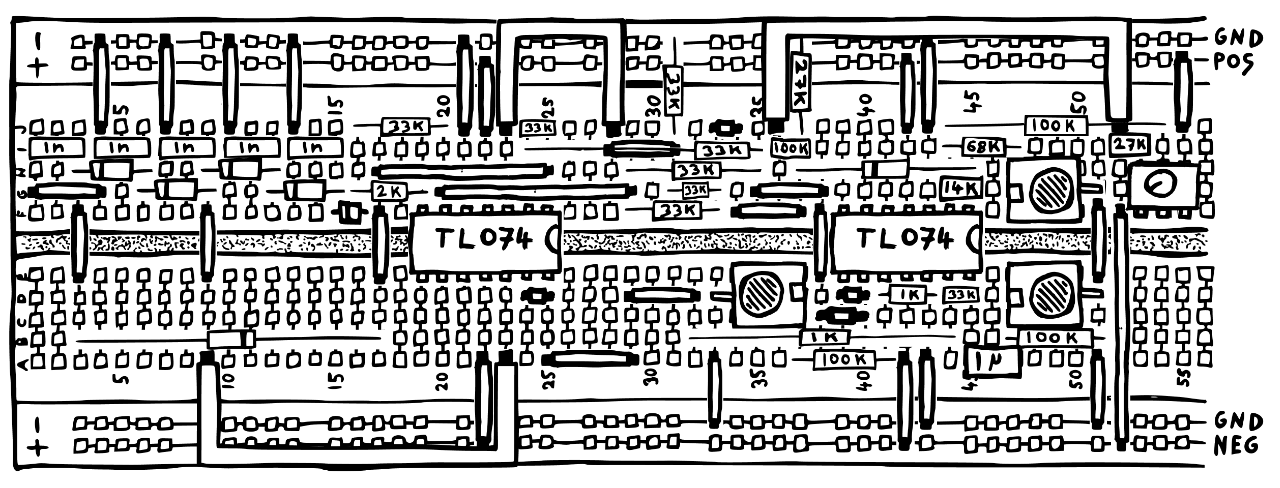
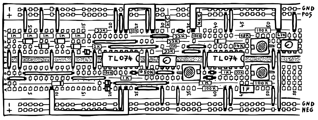
Quick, which components should I remove to go from the first to the second? Which components need to be added? No matter how carefully I work I still make mistakes. It’s another opportunity to test my debugging skills.
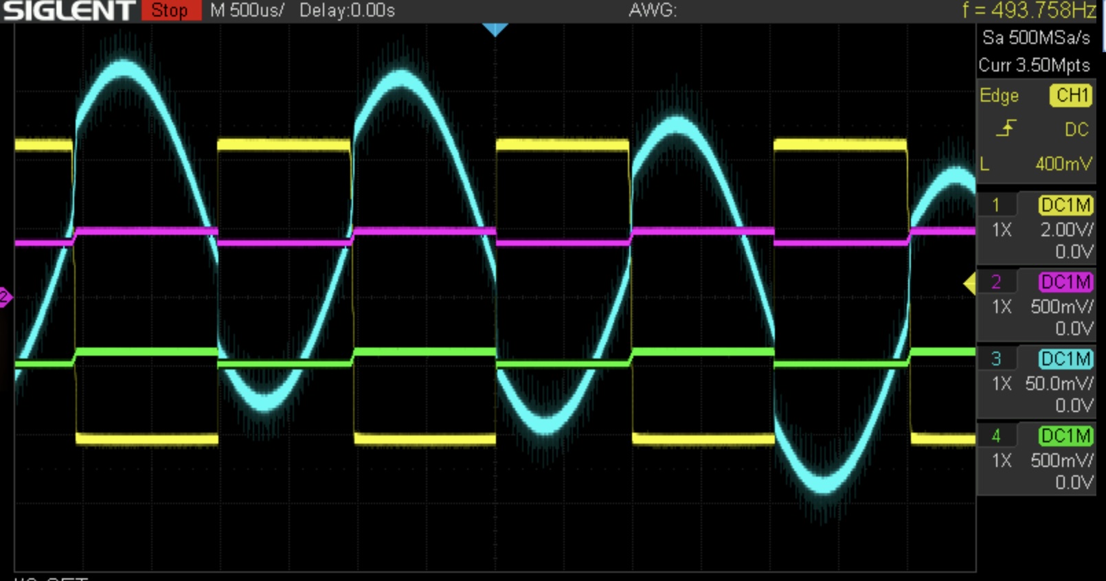
Anyway, after a lot of assembly and debugging, the output is much cleaner. Note that the cyan trace here (the filter’s output) has been switched to 500 mV/div, which is the same vertical resolution as the purple and green traces (which are the top and bottom of the diode ladder), and 10* less magnification than the 50 mv/div vertical resolution of the cyan trace (output, again) of the previous section.
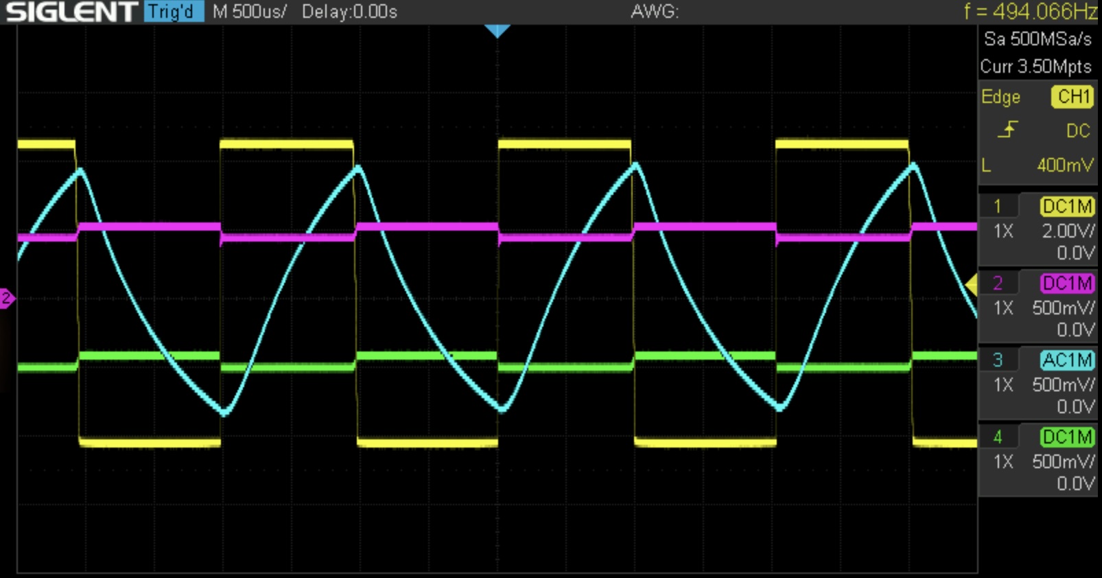
I like this because you can really clearly see how the green and purple traces get further away from each other as the filter’s cutoff gets higher and higher. This “drags the input voltage” (into either end of the diode ladder) into a different part of the diodes’ nonlinear range, making it a variable resistor, which is what we wanted.
Resonance II
The big problem that I had getting the resonance working is that I mistakenly used the Schottky diodes supplied with the kit for the power supply in place of the 1N4148 diodes that I was meant to use. The breadboard instructions just say “diode,” although they are not interchangeable! Anyway, with the correct diodes in place I can now affect the resonance a bit, although at this point every time I touched anything I would knock off the input, one of my four oscilliscope probes, a random electronic component, etc. I didn’t want to spend a lot of effort adjusting the trimpot, which is fiddly enough without all of these other cables to bump into. Still, I can see the effect of the resonance on the leading edge of the square wave here, even if it is a bit subtle:
Anyway, now we are finished with the breadboarding!
The breadboard is by now getting quite crowded. I think this kit might be better built across two breadboards.
This post is getting fairly long, so I think I will save the PC board build for next time!
Resources
Instructions
Product Pages
Community
Simulations
All of these simulations are by Moritz Klein
- Static cutoff/Variable cutoff
- Two stage LPF
- Active two-stage LPF
- Slightly resonant LPF
- Variable resonance
- Even number of stages/Odd number of stages
- Downwards shift/Upwards shift/Driving the ladder
- The output stage
- Properly processed CV
- Resonance II
Videos
- Introducing the mki x es.edu DIY VCF kit by Moritz Klein (5:04)
- Erica.EDU Diode Ladder Filter Kit! by Quincas Moreira (16:05)
The folling series of videos are iterations on the design of what is ultimately a slightly different VCF built by Moritz Klein. I do think they are useful, though:
- DIY SYNTH VCF Part 1: Analog Filtering Basics (21:45)
- DIY SYNTH VCF Part 2: Active Filters & Resonance (27:30)
- DIY SYNTH VCF Part 3: Resonant High-Pass & Vactrol-Based Voltage Control (29:20)
- Designing a diode ladder filter from scratch (36:03)
- Turning my diode ladder filter into a eurorack module (34:46)