Building a Synthesizer, 13
Building the Sequencer
- Introduction: The World of DIY Synthesizers
- 1: The mki x es.EDU DIY System
- 2: Building the Power Supply
- 3: Breadboarding the VCO
- 4: A Gentle Introduction to Op Amps
- 5: Building the VCO
- 6: The Logic Circuits Model of Computation
- 7: Building the Mixer
- 8: Building the Envelope Generator
- 9: A Field Guide to Oscillators
- 10: Building the VCA
- 11: Debugging Circuits and Software Debugging
- 12: Breadboarding the VCF
- 13: Building the VCF
- 14: Building the Sequencer
- Glossary and Electrical Connections
The mxi x es.EDU sequencer can play loops of 3, 4, or 5 notes. It can output a new control voltage, which is commonly routed to oscillator pitch, and a gate, which is commonly routed to an envelope generator, on each step of the sequence. Why 5? In the instructions, Moritz Klein says, “I simply made the decision to build a sequencer with five steps exactly,” although I suspect the fact that this is already a fairly complicated build and adding more steps would have only increased the complexity might have figured into it.
Also, why limit your sequencer to only 4 steps? This one goes to 11 5!
Commercial hardware sequencers often feature maximum sequence lengths of 16, 32, 64, or even higher number of steps, but that would make the module very large, both in terms of the number of components you would need to assemble and in terms of its physical size. As it is, this is the first module I have built from this series which requires two full-sized breadboards to prototype.
Breadboarding
The headings in this section correspond to the headings in the instructions for this kit, in case you would like to follow along.
Breadboarding the sequencer gave me a somewhat surprising amount of trouble! Part of this is due to the fact that I didn’t have two full-size breadboards available. Instead I used a full sized breadboard and two half-sized breadboards. This meant that I had to perform some mental arithmetic when connecting leads to the op amp chip, which is a great opportunity to make mistakes!
Counting with Chips and the Clock Generator
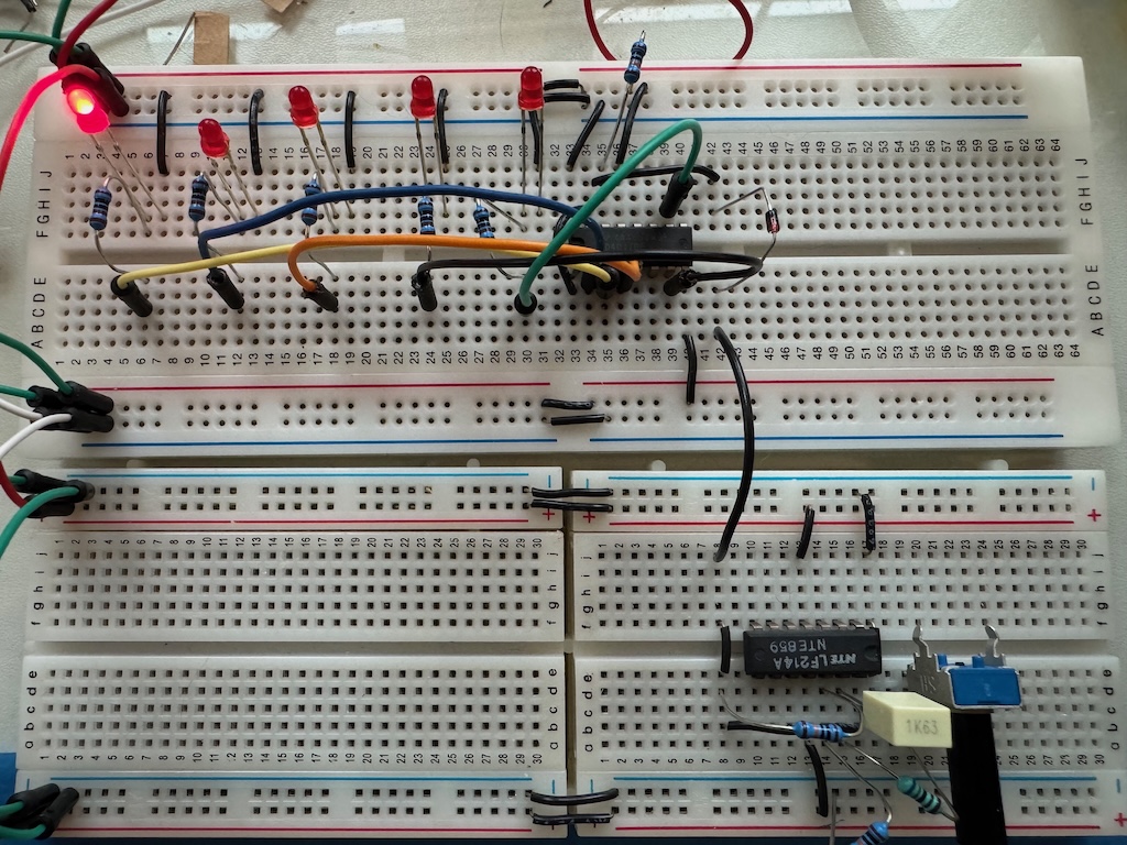
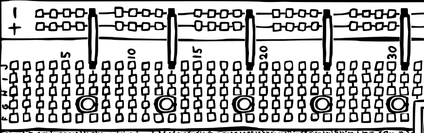
The first step is to build a five step LED counter and clock generator. When I turned on this circuit, I saw no LEDs lighting.
Well, this was a good opportunity to practice my debugging workflow. The first step is to look for obvious problems such as power. And this very well could have been the issue as this module requires two breadboards, and the power distribution of +12V, -12V, and GND across two breadboards is somewhat complex! But testing with my multimeter showed I had wired this correctly. I also checked that I had connected the correct IC pins to the power rails, which is a little bit tricky here as there are two ICs with different power pins, but I had done that correctly as well.
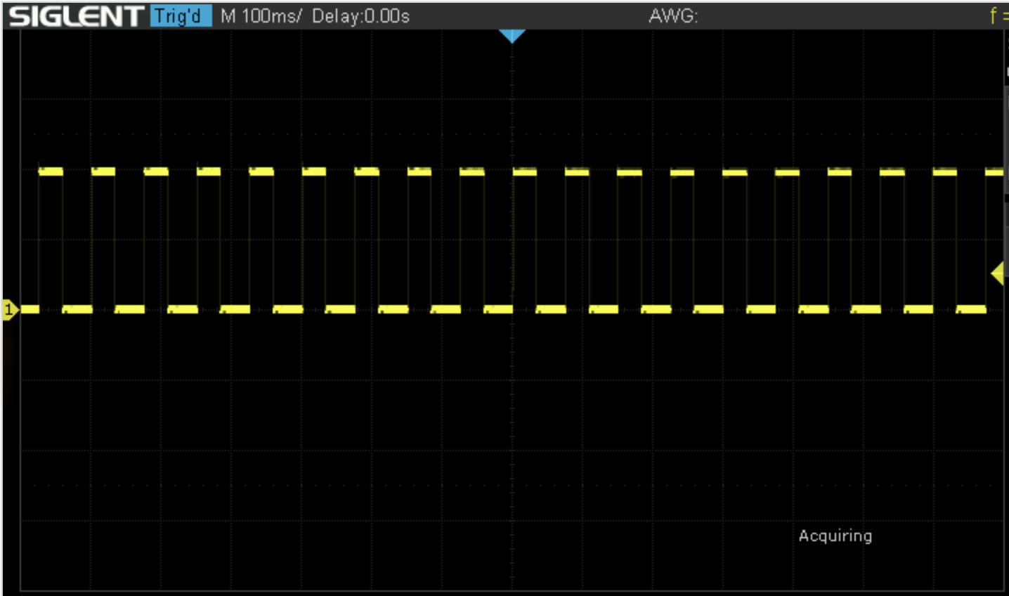
The second step is to have a model of the circuit. Here, my model is quite simple: A square wave clock generator makes the sequencer step with every pulse, causing the LEDs to light up one at a time. So given my observation that none of the LEDs were lighting up, the issue could have been that I had miswired all of them, that the sequencer IC was dead, or that the clock generator was not pulsing.
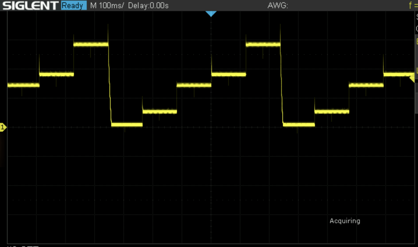
I suspected the clock generator, and testing with my oscilloscope confirmed that it was not generating a square wave. Looking closer at that IC it turned out that I had made an “off by one” error on some of the wiring on the breadboard – I had used pin 51 instead of pin 50, for example. Fixing this made the LEDs light up.
Resetting the Loop
The next step was to limit the sequence to 5 steps (instead of 8 steps, supported by the chip, but not required for this module). The instructions say:
So by connecting step six to the reset pin, we jump back to the first step as soon as we try to move past step five. Testing this on the breadboard is as easy as connecting step six and the reset pin with a jumper.
In fact, an additional step is necessary. I added a jumper as described and I found that it had no effect! I turned off the circuit, and tested continuity between the IC pins; there was no problem there. I thought that perhaps the breadboard wasn’t making a good connection, but this was fine.
(I will use this symbol ⚠ when I discuss areas where I think the instructions require clarification.)
Next, I turned on the power and tested the voltage along this wire with my oscilloscope. I saw no jump when the sequencer got to step 6, although further testing showed that it did jump on step 7 and 8. Then a light went on for me. The reason that the voltage didn’t change was that in the previous step we had wired the reset pin to ground. Jumpering the reset pin to pin 6 meant that pin 6 was now wired to ground, which is where all the electrons were now going! ⚠ So looking more closely at the instructions, the diagram does show the jumper to ground removed in this step, but it’s not mentioned in the text. Removing the connection between ground and the reset pin made the circuit work.
The CV Output
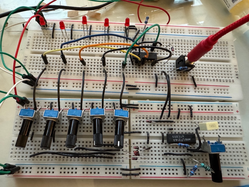
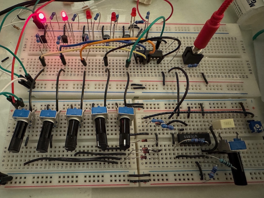
Next we (temporarily!) disconnect the LEDs and instead wire up five potentiometers for setting the pitch CV at each step of the sequence.
This was challenging due to breadboard issues. Both the “split” lower breadboard and the usual breadboard issues (poor connections) presented difficulties, but I eventually got it working. It transpired that the five potentiometers along the bottom of the board were not making good electrical contact with the inside of the breadboard, but figuring out which components were not connecting well was challenging!
CV Scaling
The next step is to scale the range of the sequencer output down from 0-12V to 0-5V. We do this by adding a resistor and a trimpot to reduce the voltage going into the buffer op amp at the output. I had a couple of problems here. The first was that the indicated placement of the trimpot was right on the border between my two half breadboards. ⚠ The second was that the indicated placement wouldn’t have worked even if I had a full-sized breadboard, because the instructions call for a trimpot which takes only a single row of the breadboard (like the trimpots supplied with other kits in this series) and there are only two rows on the breadboard free for it in the suggested layout, but the actual trimpot supplied with this kit is square and needs three rows:

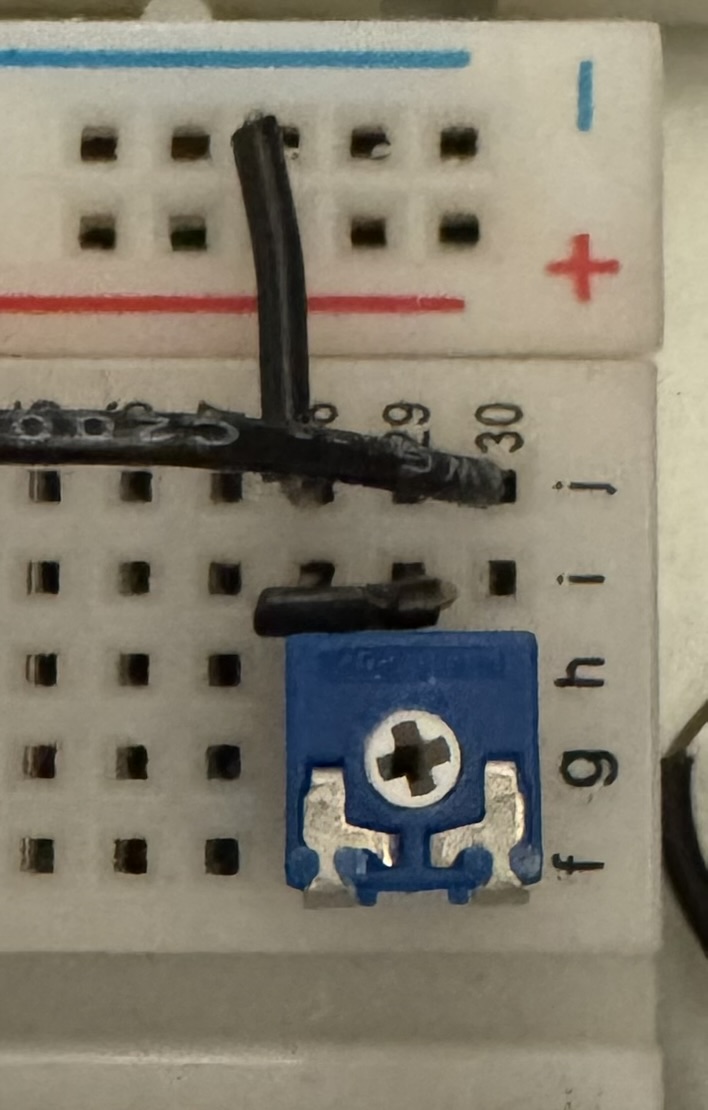
So I had to do some gymnastics with my breadboard routing.
Second, I had a momentary heart attack because the bill of materials says that two 2kΩ trimpots (and one 5kΩ) are supplied, and I only got one. ⚠ But this seems to be an error, as only one 5kΩ and one 2kΩ trimpots are needed to build or breadboard the kit.
In the end, though, everything worked, and this step gave the five potentiometers used to adjust the pitch of the sequenced notes a more useful range.
Status LEDs
⚠ Wiring the LEDs again seemed pretty simple, but at first they didn’t work. The directions, which so carefully specified their orientation when we first placed them on the breadboard, don’t mention moving them, and more importantly don’t mention that you have to rotate them 180º, which is less than obvious in the illustration:
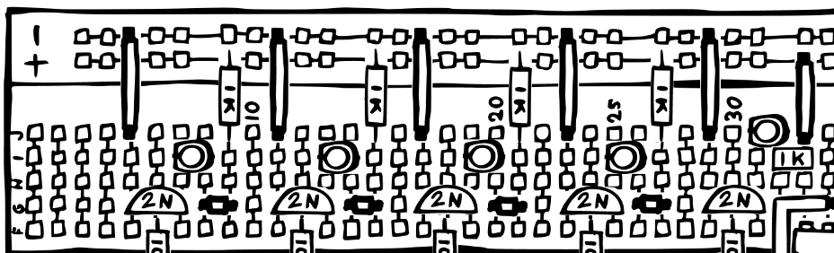
However, once I figured out what my mistake was, everything worked:
The Gate Output
I found this section of the directions a little difficult to understand until I skipped backwards in the directions to the section entitled “Sequencer Basics.” My confusion mostly stemmed from the fact that we don’t connect the gate switches when breadboarding. This is quite understandable given how full the breadboards are without them, but it made understanding the reason for the gate output sub-circuit more difficult to intuit. That section clarified how the switches were supposed to work, which, in turn, made the explanation of how this sub-circuit worked clearer. Also, looking at the simulation helped. After that, it was just a lot of wiring, which did indeed produce a square wave output at the gate jack. Which feels like a lot of work given that we already have a square wave at the clock output, but the switches, which we don’t wire when breadboarding the circuit, will allow us to “disable/suppress” some of the square wave cycles when we build the actual circuit, resulting in only some of the five notes triggering the gate output.
The Failsafe Gate Output
This step was quite easy to breadboard. In order to change the gate output from one (breadboarded in the step above) which ranges from 0V-6V to one which ranges from 0V-12V, we replace the op amp with a voltage divider at the input with a comparitor (which changes the output to either -12V or 12V), followed by a diode and resisitor (limiting the voltage to just positive values, so that it becomes either 0V or 12V), followed by a transistor emitter-follower buffer. Why this configuration (comparitor, diode, and transistor) and not just replace the op amp buffer before the gate output with an op amp in amplifier configuration? I don’t know (I guess maybe you might be concerned that an external source would give you a gate which is not a square wave, and hence you might want the comparitor in the signal path?), but in the end the circuit works well enough.
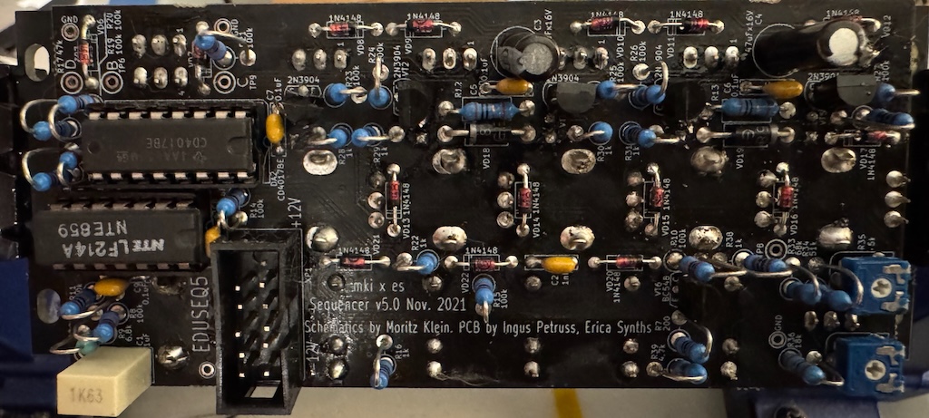
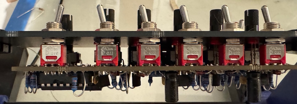
Building the Sequencer
In contrast to the other modules I have built from the mki x es.EDU series, the sequencer has only two horizontally mounted resistors, and the rest of the resistors are mounted vertically in order to squeeze all of the components onto the board. Although it doesn’t look much more complicated, perhaps due to the vertical resistors, there are probably 50% more parts on this board than in the other modules I have built so far. In general this module required more soldering than other modules from the series. Despite this, assembly went smoothly and everything worked the first time I tried powering it up.
⚠ The 1nF capacitor (C2) was ceramic, per the supplied parts and the bill of materials. However, the soldering instructions and the photos showed a film capacitor instead. Because the soldering instructions have you insert ceramic capacitors and film capacitors in separate steps, they only show 5 ceramic capacitors (C3-C8) in the first, ceramic capacitor step. This means that they don’t call out the fact that one of the supplied ceramic capacitors is a 1nF capacitor, in contrast to the remaining 5, which are 0.1µF, although all of them look identical except for the printed values on the side.
When soldering non-flush-mounted components, such as vertical resistors and transistors, I find it helpful to solder one lead, then turn the board over to correct the position of the component, then solder the other leads.
Here are some photos of the finished build:
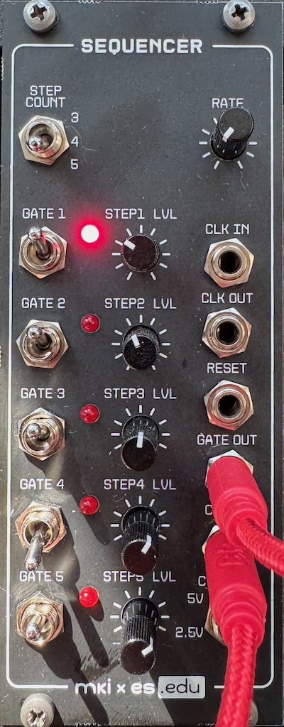
Using the sequencer is somewhat challenging as you have to set the pitch of each note – from a range of 5 octaves or so – with just a single potentiometer. And the pitch will drift as the components warm up! Analog synthesis has its advantages and disadvantages!
Resources
Instructions
Product Pages
Community
Simulations
These simulations are by Moritz Klein
- Basic Op Amp Examples/Op Amp-Based Clock
- Basic Gate to Trigger/Cut Out Negative Spike
- Scaled CV Output
- Simple Individual Gates
- Comparators/Emitter Followers/The Failsafe Gate Output
Videos
- Introducing the mki x es.edu DIY sequencer kit by Moritz Klein (5:51)
- Designing a simple 5-step sequencer from scratch by Moritz Klein (32:07)